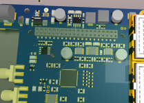
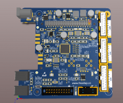
Hi guys, sorry for a lack of updates. Summertime,holidays outdoor hobbies. The big board is up and running, SPDIF out is not working, DUNNO why. Everything else is ok.
8ch dac - 2L, simple,nice, cheap, etch at home if you wish - 90% done. It needs some layout cleanup.
Sorry Mjjg I was not able to send you the board yet, I wanted to send it fully functional but got stuck on the SPDIF. I'm leaving for a 12 days vacation in about 4 hours. When I'm back holiday season is officially over for me, hopefully back to diy audio then 🙂
Best regards,
Pitrsek
Well where to start. I downloaded the kernel source and set up my build environment according to this:
https://www.raspberrypi.org/documentation/linux/kernel/building.md
I then copied the Hifiberry DAC driver and re-branded everything. It took a long time figuring out which build config files needed changing but in the end I was able to build the driver module. I then booted with the hifiberry-DAC driver loaded and checked my dmesg output. Obviously it failed to load the driver since I don't have the hardware, but there were messages about that so at least it tried. I then tried booting with my driver, but dmesg contained no indication of it being loaded. After a huge amount of digging through forums and log files I believe the cause is that the module ends up in the wrong kernel version folder. I don't have the files in front of me know so I can't check where it ended up precisely, but I can check this weekend.
I then tried branching the 4.4 kernel:
https://github.com/Mjjg/linux
I then did the changes on this clean kernel branch, but it won't boot at all, with or without my module.
Currently I'm working on redoing my attempt with the official kernel but so far no luck.
Like I said, I don't have the files here with me right now so I can't give you any details, but I'll try to collect more info this weekend.
have you loaded your driver with modprobe ?
have you loaded your driver with modprobe ?
I believe I tried that but there was some error. It was some months ago though so I'll try again this weekend and see what the exact output is.
Well whoopsi daisy, someone just had a case of the demo effect*. I retraced my steps in order to recreate the errors I had with getting the driver to load, and I discovered an embarrassing little typo in my build scripts. Now the driver loads just fine, and I can finally start working on setting it up for DSP use. Thanks for making me look closer.
*The demo effect: A situation where one tries to show someone else how something does/doesn't work, only to have said thing actually not work/work, thereby maximizing the the embarrassment for one self.
*The demo effect: A situation where one tries to show someone else how something does/doesn't work, only to have said thing actually not work/work, thereby maximizing the the embarrassment for one self.
Hi guys, sorry for a lack of updates. Summertime,holidays outdoor hobbies. The big board is up and running, SPDIF out is not working, DUNNO why. Everything else is ok.
8ch dac - 2L, simple,nice, cheap, etch at home if you wish - 90% done. It needs some layout cleanup.
Sorry Mjjg I was not able to send you the board yet, I wanted to send it fully functional but got stuck on the SPDIF. I'm leaving for a 12 days vacation in about 4 hours. When I'm back holiday season is officially over for me, hopefully back to diy audio then 🙂
Best regards,
Pitrsek
Enjoy your vacation ... but please, come back 😉
Hi, I'm implanting bug fixes & minor soldering improvements for DSP board. I need to clean up the power supplies. So, if you'd like to help me with the PiDSP project, I would really appreciate it. With your help I can concentrate on finishing the layout/design, instead of searching web pages of IC vendors and raging with frustration...
LM3370SD replacement - as vigia pointed out, it is not powerful enough, and soldering is quite demanding.
Requirements:
5V input, 3V3 and 1V2 output(adjustable option is not a problem).
two outputs, 800mA minimum per output.
diy friendly package = SO,SOIC,TSSOP, thermal pad possible - smaller package the better
enable pins
at least 1MHz switching frequency
synchronous
Nice to have:
Compensation pins
Power good
Forced PWM mode
Main 5V power supply
nominal input 12V, if we go higher we can use Pidsp in a car. So far I quite like TPS54360, but I'm open to another suggestions. I haven't have time to go through the TPS54360 datasheet in full detail yet.
Requirements:
5V output(again, fb divider is not a problem)
3A
enable
compensation pin
Nice to have:
Power good
Forced PWM mode
synchronous
Thx for your help
Take a look at TPS70345 for DSP supply. I'm also desining a board based on ADAU1452 and AK4458 DAC chip.
It is a nice regulator with power good option and Power-On Reset. It also have reset inputs for the external programer or manual reset.
But it is not switching
It is a nice regulator with power good option and Power-On Reset. It also have reset inputs for the external programer or manual reset.
But it is not switching
LM26420X is in TSSOP-20, synchronous, has 2x2A capability, 2MHz and separate enable and power-good so you can do sequencing. Few external components. It's <$3 in quantity 100.
LM20343 is also in TSSOP-20, synchronous, has 3A output capability and 36V input range. Enable, power-good and comp pin. <$4 in quantity 100.
TPS54360 is a good choice if you don't think you need synchronous or power-good pin. And it's in SOIC-8 package which is very diy-friendly.
LM20343 is also in TSSOP-20, synchronous, has 3A output capability and 36V input range. Enable, power-good and comp pin. <$4 in quantity 100.
TPS54360 is a good choice if you don't think you need synchronous or power-good pin. And it's in SOIC-8 package which is very diy-friendly.
So new regulators are TPS54292 and TPS54360. I've tweaked the PDN impedance a bit(simulation does not include mounting inductance), fixed more bugs, and unified some component values for smaller BOM. New footprint for ADAU is also underway - with longer pads for easier soldering.
Attachments

Schematics review
I've cleaned up schematics enough for a review 🙂. Please take a look and let me know what you think.
Quite few values are still TBD - the either need to be calculated(enough time for that while we wait for PCBs), or selected after testing(snubbers).
I've cleaned up schematics enough for a review 🙂. Please take a look and let me know what you think.
Quite few values are still TBD - the either need to be calculated(enough time for that while we wait for PCBs), or selected after testing(snubbers).
Attachments
Last edited:
I quickly looked through the schematics, and at first glance they seem to be in order. I will try to take a more detailed look at them in the next few days.
I've cleaned up schematics enough for a review 🙂. Please take a look and let me know what you think.
Quite few values are still TBD - the either need to be calculated(enough time for that while we wait for PCBs), or selected after testing(snubbers).
Hi Pitrsek,
very good job. Congratulations.
With regards to the pdf, how will you manage external clocks? Do you have in mind a single frequency or multiple frequencies?
Hifiberry DAC PRO has 2 oscillators and the linux driver is capable to select the oscillator according to the sample frequency. It is done with GPIO. Advantages is to have 2 dedicated clocks for samples : 44khz or x48khz
Here is an extract of the linux driver:
switch (clk_id) { + case HIFIBERRY_DACPRO_NOCLOCK: + snd_soc_update_bits(codec, PCM512x_GPIO_CONTROL_1, 0x24, 0x00); + break; + case HIFIBERRY_DACPRO_CLK44EN: + snd_soc_update_bits(codec, PCM512x_GPIO_CONTROL_1, 0x24, 0x20); + break; + case HIFIBERRY_DACPRO_CLK48EN: + snd_soc_update_bits(codec, PCM512x_GPIO_CONTROL_1, 0x24, 0x04); + break; + }
2/ I was able to program the freedspv1 EPROM from a RPI, by I2C. Will it be possible to do the same?
Regards,
Christian
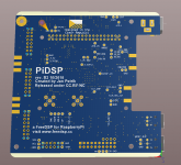
Hi, DRC is clear. Sebastian has created a very nice logo for my board - thank you Sebastian!. I'll check the board one more time tomorrow, add new logo and I'll order the boards  .
.
Next in line will be cleanup of the components(lot of them are missing PN), and release of the source files(the board is going to be released under CC BY-NC. ). The idea is to release source files within next week or two, so you can order your board and have it on hand before Xmas. For a perfect Xmas time with soldering iron in your hands 😉. All components with exception of xtal are available from mouser/farnell. Oscillators are available on ebay or on various DIY stores.
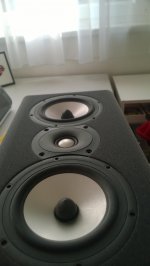
Oh, I've also made some progress with my speakers.
@Mjjg thx for the check.
@camelator - please see this thread for discussion about clocks. In short, I'm going to use only one, Mjjg and others were interested in second one and ability to switch them. So I added support for 2nd oscillator. You can join them with the driver effort if you'd like. It's same here, you can switch oscillator with GPIO, or select external clock source.
Programing from RPI - self boot eeprom is connected only to ADAU i2c master bus. ADAU i2c slave bus is connected to RPI. boot select and reset are connected to RPI GPIO. You should be able to program the EEPROM from RPI(write through).
.Next in line will be cleanup of the components(lot of them are missing PN), and release of the source files(the board is going to be released under CC BY-NC. ). The idea is to release source files within next week or two, so you can order your board and have it on hand before Xmas. For a perfect Xmas time with soldering iron in your hands 😉. All components with exception of xtal are available from mouser/farnell. Oscillators are available on ebay or on various DIY stores.
Oh, I've also made some progress with my speakers.
@Mjjg thx for the check.
@camelator - please see this thread for discussion about clocks. In short, I'm going to use only one, Mjjg and others were interested in second one and ability to switch them. So I added support for 2nd oscillator. You can join them with the driver effort if you'd like. It's same here, you can switch oscillator with GPIO, or select external clock source.
Programing from RPI - self boot eeprom is connected only to ADAU i2c master bus. ADAU i2c slave bus is connected to RPI. boot select and reset are connected to RPI GPIO. You should be able to program the EEPROM from RPI(write through).
Attachments

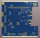
gerbers
Hi,
I've ordered the boards. For those who can't wait, see the attachment for gerber files - you can order your own board. To my knowledge the board is ready to go, but I haven't had a chance to test it. Rest of the documentation - Altium project, BOM, documentation will follow. I'm leaving for a 10 day hiking trip to Georgia . I'll get back to PiDSP when I'm back.
Jan
Hi,
I've ordered the boards. For those who can't wait, see the attachment for gerber files - you can order your own board. To my knowledge the board is ready to go, but I haven't had a chance to test it. Rest of the documentation - Altium project, BOM, documentation will follow. I'm leaving for a 10 day hiking trip to Georgia
. I'll get back to PiDSP when I'm back.Jan
Attachments
Thank Pitrsek , great stuff !!
I look forward to the rest of the documentation. Enjoy your hiking !! well deserved
Cheers
Pepe
I look forward to the rest of the documentation. Enjoy your hiking !! well deserved
Cheers
Pepe
Hello,
I am very interrested in these diy dsp projects, can i please ask a question?
I am working on a project, not related to hifi audio, instead i am interrested i ultrasound in the frequency range around 11 khz to 40-50 khz, and to do various filtering test in this frequency range.
Will any of these diy dsp projects be able to handle and process sound this frequency range or are all these projects limited to audio use, cutting off at 20-24 khz?
Hi,
ADAU1452 supports up to 192kHz sample rate. If you provide suitable DA and AD converters, you can process 40-50khz signal with PiDSP with no problem.
ADAU1452 supports up to 192kHz sample rate. If you provide suitable DA and AD converters, you can process 40-50khz signal with PiDSP with no problem.


- Home
- Source & Line
- Digital Line Level
- freeDSP V2.0 (ADAU1452) developement thread