I've been looking into the Linux kernel driver on and off over the last month. Took a while to read up on device trees and the clock architecture and so on, but I'm at a point where I can start to write actual code for it. So as soon as there is a working version of the DSP board available, I'd be interested in buying one. Preferably populated though, that soldering is a bit too much for my taste. I don't need any DAC board at this stage, that can come later.
This is going to be quite a big chunk of work. Biggest part is implementing a device driver for the ADAU1452. Patching everything up in a sound driver will be the minor part.
This is going to be quite a big chunk of work. Biggest part is implementing a device driver for the ADAU1452. Patching everything up in a sound driver will be the minor part.
I dream of a DSP connected to a raspberry for a long time.
I am a good C++ developper.
I have a rpi as well.
I can help if you need it.
I am a good C++ developper.
I have a rpi as well.
I can help if you need it.
@Mjjg
That's excellent news. I've decided to populate rest of the small PiDSP boards as well. I need to solder THT parts, big capacitors, and test the boards. Hopefully it will be done by next weekend.
I can agree that soldering is a bit on the tough side - I've had problem with the 4 resistors in one package - I had to re-solder almost everyone of them. Don't know weather the problem was my paste printing or thermal profile(lack of it, more or less, I've used hot air gun).
Small board does not have the second clock source, but at least you'll have some hw to work on 🙂. I'll put one small board aside for you.
@camelator
Hi, help is always welcome. Do you think you could create a program that would upload firmware to the DSP EEProm from RPI? You might want to have chat with Mjjg, it seems that he is quite far with his efforts. Actually I do not know what functionality is he envisioning for his driver.
@Mjjg - do you plan to boot the dsp via I2C bus from the RPi as a part of your driver?
Attachments
@camelator
Yes, help would be very much appreciated. I have some experience with a lot of different programming languages, but I'm hardly an expert in any of them. And I've never dabbled with the Linux kernel before. So any help with either the driver, or the programming interface would be much appreciated.
@Pitrsek
That sounds great 🙂
I'm not sure yet how the boot process will look like. But one thought I have is to let the DSP self-boot from the EEPROM. For the simple clock case (all resampling in the R-PI) that's the straight forward approach anyway. For the case of different clock sources, I'm thinking we could load all versions of the program into the EEPROM (one for each clock setup). Each setup consists of a header, configuration data and a footer. The self boot process always reads the header from address 0, and it contains the address of the start of the data block. Boot process stops after the footer, which comes right after the data block, is detected. So if we save all setups to EEPROM, plus some metadata of our own, we can let the pi read the metadata and write a header at address 0, pointing to the right setup. From a driver perspective, this would be a very neat solution. But of course the EEPROM has to be large enough to handle all setups, and the software that writes the EEPROM must handle concatenating all the data and generate the metadata. The metadata would indicate to the Pi what setups are in the EEPROM, at what addresses, and which fs they are for. This is just a suggestion, and any thoughts on this is welcome. I've also thought about googlyone's suggestion to parse the biquad filter setup from the sigmastudio output and just update the DSP directly from the Pi. But there might be some issues with that. First and foremost, it's not so easy to read files from a kernel driver. From what I gather, you have to connect kernel space and user space over sysfs somehow. I have no clue how all that would work but if anyone has an idea I'd be all ears.
Another issue we need to think about here is branding. The driver registers the DSP card using a vendor/model string. Since the most reasonable approach IMO is to use one driver per clocking scenario, I guess we would use PiDSP as the base name, and add some identifier for the operational mode, for example:
Basic mode, one clock frequency: PiDSP
Extended mode, two clocks, integer resampling: PiDSP+
Pro mode, two clocks, individual clock setup on a per input base: PiDSP++
Or something like that. But what about vendor? I get the feeling this is a pure hobby project...
@Mjjg
That's excellent news. I've decided to populate rest of the small PiDSP boards as well. I need to solder THT parts, big capacitors, and test the boards. Hopefully it will be done by next weekend.
I can agree that soldering is a bit on the tough side - I've had problem with the 4 resistors in one package - I had to re-solder almost everyone of them. Don't know weather the problem was my paste printing or thermal profile(lack of it, more or less, I've used hot air gun).
Small board does not have the second clock source, but at least you'll have some hw to work on 🙂. I'll put one small board aside for you.
@camelator
Hi, help is always welcome. Do you think you could create a program that would upload firmware to the DSP EEProm from RPI? You might want to have chat with Mjjg, it seems that he is quite far with his efforts. Actually I do not know what functionality is he envisioning for his driver.
@Mjjg - do you plan to boot the dsp via I2C bus from the RPi as a part of your driver?
Hi Pitrsek,
Great news you have the PCB's, very exciting.
I am confused how the PiDSP will be used in an active speaker, how many inputs you get etc?
What are the advantages over the stand alone INSANITY 8 x Analog PCB.
I understand at the moment Sigma Studio would have to be used from PC, so am a little unsure which board I would need for a 3 way active speaker, with volume control and an analogue input.
Many thanks
Ian
Hi guys,
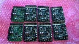
sorry for being absent for so long. My decision to populate rest of the boards bite me in my posterior, big time... all the soldering, testing, more soldering,more testing....
Unnecessary to say, I made some mistakes and learned few things in the process. Should I do something similarly crazy, I'll probably hack together a re-flow Owen before I start soldering. And get a binocular magnifier. eh, enough bitching.
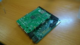
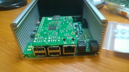
Some boards are ready and tested, I'm waiting for oscillators to arrive to finish the rest. New version is almost populated and is in the testing process.
In a meantime, new raspberry pi has arrived, and UpBoard, which seems to bee compatible too 🙂
For others working with ADAU145x - watch out for power supply sequencing and POR. My core supply and IO supply starts simultaneously, and as such 1v2 is ready before IO. Which is sub-optimal(dataseet page25). Another unfortunate result is that master POR does not seem to work properly. Master POR might work if sequencing was correct, dunno. I've settle with POR signal from buck converter.
Also watch out for EEPROMs - some vendors include pull-downs on WP, some don't. Also some wants you to externally hard-wire 3rd address bit.... yes all of it is in the datasheet, i know...
@Mjjg
So far it is a hobby project(and biggest that I've ever done), but the experience with soldering 15 boards(13 small + 2 big/new) showed to me that it is not really "solder at home" friendly. You need a good magnifier, and hot air gun/IR, preferably preheat...
I believe that we might be able to generate enough interest to have a batch of boards made in assembly house. And then you need to design testing procedure, test boards, ship them... and suddenly it is quite blurry weather it is hobby project or small business...
@webby
With PiDSP you have 3+1 I2S I/O + SPDIF I/O. The +1 is connected to raspberry pi - so you can just plug RPi and have music player. 3 I2S I/O are on freedsp standardized header. If you wish not to use RPi, you can use all four. Regarding difference the difference with INSANITY.
PiDSP is designed as a basic building block of a modular system, insanity is more of all in one kind of solution. Further more PiDSP, as a name suggest is geared towards symbiosis with RPi(or any other compatible SBC), so if you decide to invest 35buck for RPi, you can have an independent music/movies player. Which I find rather nice. PiDSP does provide power(&power management) for RPi and can provide elegant connections for front panel user interface if you need.
At the moment I can not offer you an analog input board for PiDSP. But you can connect any ADC board that supports I2S 🙂. There is rather nice eval board from TI - pcm4222EVM. I might get to ADC board someday. If you(or anybody else) wish to design the ADC board yourselves, I'll be happy to give you few advice&help with as far as reviews, bitching and comments goes.
I'm working on PiDSP and DAC board ATM, and as you can see, pace of my "Sunday evening engineering" is just as name suggest, nothing stellar. On the upside, I'm still working on it after more than a year. Which, for me at least, is kinda surprising 😀
Jan
sorry for being absent for so long. My decision to populate rest of the boards bite me in my posterior, big time... all the soldering, testing, more soldering,more testing....
Unnecessary to say, I made some mistakes and learned few things in the process. Should I do something similarly crazy, I'll probably hack together a re-flow Owen before I start soldering. And get a binocular magnifier. eh, enough bitching.
Some boards are ready and tested, I'm waiting for oscillators to arrive to finish the rest. New version is almost populated and is in the testing process.
In a meantime, new raspberry pi has arrived, and UpBoard, which seems to bee compatible too 🙂
For others working with ADAU145x - watch out for power supply sequencing and POR. My core supply and IO supply starts simultaneously, and as such 1v2 is ready before IO. Which is sub-optimal(dataseet page25). Another unfortunate result is that master POR does not seem to work properly. Master POR might work if sequencing was correct, dunno. I've settle with POR signal from buck converter.
Also watch out for EEPROMs - some vendors include pull-downs on WP, some don't. Also some wants you to externally hard-wire 3rd address bit.... yes all of it is in the datasheet, i know...
@Mjjg
So far it is a hobby project(and biggest that I've ever done), but the experience with soldering 15 boards(13 small + 2 big/new) showed to me that it is not really "solder at home" friendly. You need a good magnifier, and hot air gun/IR, preferably preheat...
I believe that we might be able to generate enough interest to have a batch of boards made in assembly house. And then you need to design testing procedure, test boards, ship them... and suddenly it is quite blurry weather it is hobby project or small business...
@webby
With PiDSP you have 3+1 I2S I/O + SPDIF I/O. The +1 is connected to raspberry pi - so you can just plug RPi and have music player. 3 I2S I/O are on freedsp standardized header. If you wish not to use RPi, you can use all four. Regarding difference the difference with INSANITY.
PiDSP is designed as a basic building block of a modular system, insanity is more of all in one kind of solution. Further more PiDSP, as a name suggest is geared towards symbiosis with RPi(or any other compatible SBC), so if you decide to invest 35buck for RPi, you can have an independent music/movies player. Which I find rather nice. PiDSP does provide power(&power management) for RPi and can provide elegant connections for front panel user interface if you need.
At the moment I can not offer you an analog input board for PiDSP. But you can connect any ADC board that supports I2S 🙂. There is rather nice eval board from TI - pcm4222EVM. I might get to ADC board someday. If you(or anybody else) wish to design the ADC board yourselves, I'll be happy to give you few advice&help with as far as reviews, bitching and comments goes.
I'm working on PiDSP and DAC board ATM, and as you can see, pace of my "Sunday evening engineering" is just as name suggest, nothing stellar. On the upside, I'm still working on it after more than a year. Which, for me at least, is kinda surprising 😀
Jan
Attachments
Wow! Very nice, that is a _lot_ of work!
Thanks for the heads-up about the ADAU145x to other developers.
As for manufacturing, yes it is a bit blurry whether it is a hobby or a small business at some point. If you want to stay closer to hobby then I think there are a few options:
1. Make some small changes to the board so that it would be easier for skilled DIY'ers to solder it themselves and then sell just the bare PCB, or just publish the design. Unfortunately a lot of potential buyers will be scared off by this.
2. Sell a manufactured and soldered PCB but without warranty and without production-testing. As long as you have tested the prototype good enough and verified that it will work as long as it is soldered correctly, then the chances of a factory made board working is high enough for hobbyist use. Start with a small batch.
3. Only have the most fine-pitch parts soldered by a factory and let the buyer solder the rest of the parts.
4. Partner up with someone that already does this as a small business such as TwistedPear or others and let them handle the entire manufacturing and shipping.
Hi Pitrsek,
take a look into AN-772.
It is much easier to solder it with enlarged pads, particularly with PB free solder paste.
take a look into AN-772.
It is much easier to solder it with enlarged pads, particularly with PB free solder paste.
An externally hosted image should be here but it was not working when we last tested it.
@Fio - definitely good idea, thank you. the ADAU footprint I used was generated as nominal per IPC. It's solder-able, but not really friendly.
Yes it was... and I have 5 more waiting for oscillators and some misc parts. and clean up and testing....
I'll tune it up a bit so it is more hand solder-able, that's for sure. After 7 boards I know where are the rough spots. I rather like your option number two.
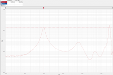
I've played with Bode 100 and measured output impedance of the regulators on PiDSP.
LP5907 3.3V@20mA - low frequency output impedance is cca 80mOhm, if you adhere to the datasheet and use only 1uF output capacitor, you'll have really nice impedance bump(cca 300mOhm). If you want flat impedance, you need to increase output capacitance roughly 100 times 🙂. I have suitable 100uF capacitor(with 80mOhm ESR) on the way. This should result in nice flat impedance. I'll post measurements when it's soldered&tested.
lm3370 - output impedance is burred in noise, I would estimate it to be around 10mOhm. Problem with such low output impedance is that it's very hard to attain flat impedance. Alas there is no compensation pin on LM3370 that would allow me to increase its output impedance. Even with 390uF the impedance peaking is quite sever. It's quite hard to measure such low impedance.
I'm still looking for the short on the big board, I've found quite nice way how to search for it - I'll probably give it a try.
Wow! Very nice, that is a _lot_ of work!
Thanks for the heads-up about the ADAU145x to other developers.
As for manufacturing, yes it is a bit blurry whether it is a hobby or a small business at some point. If you want to stay closer to hobby then I think there are a few options:
...
Yes it was... and I have 5 more waiting for oscillators and some misc parts. and clean up and testing....
I'll tune it up a bit so it is more hand solder-able, that's for sure. After 7 boards I know where are the rough spots. I rather like your option number two.
I've played with Bode 100 and measured output impedance of the regulators on PiDSP.
LP5907 3.3V@20mA - low frequency output impedance is cca 80mOhm, if you adhere to the datasheet and use only 1uF output capacitor, you'll have really nice impedance bump(cca 300mOhm). If you want flat impedance, you need to increase output capacitance roughly 100 times 🙂. I have suitable 100uF capacitor(with 80mOhm ESR) on the way. This should result in nice flat impedance. I'll post measurements when it's soldered&tested.
lm3370 - output impedance is burred in noise, I would estimate it to be around 10mOhm. Problem with such low output impedance is that it's very hard to attain flat impedance. Alas there is no compensation pin on LM3370 that would allow me to increase its output impedance. Even with 390uF the impedance peaking is quite sever. It's quite hard to measure such low impedance.
I'm still looking for the short on the big board, I've found quite nice way how to search for it - I'll probably give it a try.
Excellent project Pitrsek, maybe im late, about the power supply, in the schematic there are 2 L6986, 1 unpopulated. You can use a TPS54335, it give you 3A, another issue could be the LM3370, it give you max 600ma. If you see the ADAU145x datasheet page 7, using the full program the max in DVDD could reach 690ma, the is no curve in the datasheet that show us temperature current so is good to make some test, taking in account that maybe the solder to the heatsink is no excellent we could see a raise en the current. So if you take out one L6986, you have space tu use TPS56220x with 2A to spare to generate 1.2v. and you can use the enable to have a better control of the boot sequence.
Hi vigia,
nice catch with the load current, thank you. I've managed to measure output impedance of LM3370 - it's actually 6mOhms, and it's probably going out... I have a replacement in mind(NCP3170), but I need to test it first. If I like it I'll probably replace L6986 with NCP3170 too. It's 3A converter, with easy to solder package.
After that, only IC with thermal pad will be the DSP. The package/thermal pad is big enough for a decent hole from bottom, so you can solder it from bottom. Generally, I'm taking notes on hard to solder spots, whats problematic etc., I hope that the next and final version will be rather DIY friendly.
I've discovered two bugs on big version - swapped pins in power jack symbol, and enable pull up for a voltage regulator connected to its output. I'm yet to test the dual L6986.
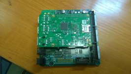
Oh, and I've spent some time with DAC board.
nice catch with the load current, thank you. I've managed to measure output impedance of LM3370 - it's actually 6mOhms, and it's probably going out... I have a replacement in mind(NCP3170), but I need to test it first. If I like it I'll probably replace L6986 with NCP3170 too. It's 3A converter, with easy to solder package.
After that, only IC with thermal pad will be the DSP. The package/thermal pad is big enough for a decent hole from bottom, so you can solder it from bottom. Generally, I'm taking notes on hard to solder spots, whats problematic etc., I hope that the next and final version will be rather DIY friendly.
I've discovered two bugs on big version - swapped pins in power jack symbol, and enable pull up for a voltage regulator connected to its output. I'm yet to test the dual L6986.
Oh, and I've spent some time with DAC board.
Attachments
Thats really good Pitrsek, other thing to keep in mind for your next revision, if you have and expansión port for freedsp IO cards, you have to supply them with 12 volts. its in their guidelines.
12V is already provided for Freedsp header 🙂. I spent some time today searching for automotive grade 3A buck, so one can plug PiDSP to car battery without worry. It seems that there are some options...
Few observations regarding eeproms:
Self-boot eeprom has fixed address of 0x50, address settings in sigma studio have no bearing on this. Additionally, for I2c selfboot ADAU1452 supports "only" 512kb EEPROM.
I aimed to make board to accept OnSemi and Microchip - two vendors I had on hand. By providing required connections for Microchip EEprom I changed address for OnSemi... Dunno what is the situation with other vendors, it's just one of the things to watch out...
Also, SPDIF out is biased to IOVDD/2, same as input...
I too hope the hardware development is progressing as planned. I'm very excited about this project.
I gave myself the task to look into the kernel driver for the raspberry. Unfortunately that is going quite bad. After several attempts at it from various attack vectors, I simply can't get the kernel to load my driver (or even boot at all in some cases). I've never done any programming for the linux kernel before so that might not be terribly surprising. Is there anyone on this thread that have dabbled with linux kernel drivers that would be willing to lend a hand? If so, please PM me.
I gave myself the task to look into the kernel driver for the raspberry. Unfortunately that is going quite bad. After several attempts at it from various attack vectors, I simply can't get the kernel to load my driver (or even boot at all in some cases). I've never done any programming for the linux kernel before so that might not be terribly surprising. Is there anyone on this thread that have dabbled with linux kernel drivers that would be willing to lend a hand? If so, please PM me.
I too hope the hardware development is progressing as planned. I'm very excited about this project.
I gave myself the task to look into the kernel driver for the raspberry. Unfortunately that is going quite bad. After several attempts at it from various attack vectors, I simply can't get the kernel to load my driver (or even boot at all in some cases). I've never done any programming for the linux kernel before so that might not be terribly surprising. Is there anyone on this thread that have dabbled with linux kernel drivers that would be willing to lend a hand? If so, please PM me.
Hi Mjjg,
lot of possible issues... please post a step by step process for comments.
Well where to start. I downloaded the kernel source and set up my build environment according to this:
https://www.raspberrypi.org/documentation/linux/kernel/building.md
I then copied the Hifiberry DAC driver and re-branded everything. It took a long time figuring out which build config files needed changing but in the end I was able to build the driver module. I then booted with the hifiberry-DAC driver loaded and checked my dmesg output. Obviously it failed to load the driver since I don't have the hardware, but there were messages about that so at least it tried. I then tried booting with my driver, but dmesg contained no indication of it being loaded. After a huge amount of digging through forums and log files I believe the cause is that the module ends up in the wrong kernel version folder. I don't have the files in front of me know so I can't check where it ended up precisely, but I can check this weekend.
I then tried branching the 4.4 kernel:
https://github.com/Mjjg/linux
I then did the changes on this clean kernel branch, but it won't boot at all, with or without my module.
Currently I'm working on redoing my attempt with the official kernel but so far no luck.
Like I said, I don't have the files here with me right now so I can't give you any details, but I'll try to collect more info this weekend.
- Home
- Source & Line
- Digital Line Level
- freeDSP V2.0 (ADAU1452) developement thread