I am also interested in this DSP project. In the first post you have mentioned many different DAC-s and other components that you might use. I understand that the design has changed over time. Could you tell me what components does the final product use? I would like to know how many output channels does it have? And if it can output i2s or will it have built in DAC. Maybe you could post an update on the final specs sheet.
Also could you please tell me if build kits or fully assambled boards will be offerd once the testing has been compleeted?
Also could you please tell me if build kits or fully assambled boards will be offerd once the testing has been compleeted?
How is the project going? Did you get the board up and running?
I am interested in possibly getting involved. Altho I use Eagle. I would be open to doing an Eagle Layout if I could get some feedback from more knowledge members on the layout. 😎
I am interested in possibly getting involved. Altho I use Eagle. I would be open to doing an Eagle Layout if I could get some feedback from more knowledge members on the layout. 😎
Hi guys, sorry for long pause.
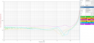
I finally managed to fine tune the output impedance of the regulators. The dips in the impedance are results of big MLCC - 10uF and 2uF respectively. The ESR is in reality way smaller than stated in the datasheet. Speaking about differences between reality and datasheet - I had to degrade specs for 5V buck. Original target was 5v@3A, but it's too hot for sustained load. I had to reduce inductance, reduce switching freq. and reduce rating to 2.5A. I went with too small(package) inductance and did not bothered to sample/measure it before hand. Oh, and since the buck is at the edge of pcb, the cooling is also bit worse than expected. Who would though, you if you place your IC at the edge of the board and place a big 2.54mm connector on the other side, cooling sux.... 🙂
Moral of the story? Before you use new component, measure/validate it first....
Oh and PCBs for thermal characterization are rather bigger than you would imagine... But you need to bother to open the appnote and read about it 😛
I made f*** up 1v2 plane a bit - added testpoints and pullups and plane got separated. Impedance is a bit bigger than planned - but nothing serious.
I've managed to finish my speakers - well, right one at lest, i still need to screw in the drivers for left one. Spdif from PC, PiDSP and ES9018 from ebay - lot of observations about this little board. I'll probably post a thread about it in future.
BTW. I've started to built these speakers for my university thesis 6years ago...
I'll populate rest(basically just the dsp and ESD protection, everything else is already soldered) of the blue board and test it this week. I'm filing PN and cleaning up schematics. When it's done, I'll incorporate changes and erratas(one wire jumper, the plane mistake, and few components soldered atop each other). Reason for this approach is that I'd like to have a correct schematics for the blue board.
I've also paid for hosting and domain, hopefully it will motivate me to be a little more active.
@Infinity656
The board dosing haven't changed for some time 3 I2s io on FreeDSP connector(i2s,i2c,power), 1 I2S to RPI header, front panel connector, toslink in&out, power-management.
I'll be researching production run when I have cleared the schematics/bom. If you have a favorite manufacturer for small pcb runs, please share.
Take care,
Pitrsek 🙂
Attachments

Hello iampoor,
If you'd like to help/join in, you could design the front panel control board. There is nothing serious/complicated. 4 potentiometers, 4 buttons, power button, IR for RPi and maybe LCD for rpi if you'd like... Or subset of it. Or you could go for a DAC/ADC.
If you'd like to help/join in, you could design the front panel control board. There is nothing serious/complicated. 4 potentiometers, 4 buttons, power button, IR for RPi and maybe LCD for rpi if you'd like... Or subset of it. Or you could go for a DAC/ADC.
How is the project going? Did you get the board up and running?
I am interested in possibly getting involved. Altho I use Eagle. I would be open to doing an Eagle Layout if I could get some feedback from more knowledge members on the layout. 😎
i've used pcbway.com for small runs. the disadvantage is that you may need to provide the exotic parts, and they have to pay import duties on the parts.
enclosed a pcbway frontpanel I did as standard PCB with black soldermask.
I used nut inserts at the back to be soldered in.
enclosed a pcbway frontpanel I did as standard PCB with black soldermask.
I used nut inserts at the back to be soldered in.
Attachments

Nice Pitrsek, its good that everything is working, about the temperature, you are using 1 or 2 oz copper pcb?
The path forward?
Do you have any backchannel communications with the driver team? Is it time to recruit a Linux kernel hacker with audio/dsp and driver experience? (I know just the person but he is very busy!)
Based on your performance calculations that you posted, a 2 way XO taking 6% of the DSP capability will leave the DSP underutilized for some use cases. For XO type work, the current board and DSP should be able to handle >7.1 audio processing at ~50% DSP load. In this XO use case, the limit of qty 4 i2s channels will be the ultimate limiting factor on useability. Of course, at 7.1 processing, this board is still the digital equivalent of the $500 4x10 miniDSP, but this DSP could exceed the miniDSP.
With the next generation Sigma DSP probably just around the corner (the current DSP is 3 years old) it would be nice to be able to 'drop in' an upgrade DSP to handle more IO and more signal processing.
Based on the current and projected DSP performance, I think that ~20 channels would be the sweet spot for a version X of the board. For the current DSP, 20 channels would max out the DSP capabilities for 2 way XO. For future Sigma DSPs, 20 channels would probably max out the capabilities for XO and correction capabilities combined.
Of course, version 1.0 of this board is eagerly awaited...
There are many threads to be woven together. I'm curious about clock syncing from an external source and then sharing that with the DAC. It seems that hacking through some of the code that's generated by Sigma Studio will be necessary?Hi guys, sorry for long pause.
I've managed to finish my speakers - well, right one at lest, i still need to screw in the drivers for left one. Spdif from PC, PiDSP and ES9018 from ebay - lot of observations about this little board. I'll probably post a thread about it in future.
Do you have any backchannel communications with the driver team? Is it time to recruit a Linux kernel hacker with audio/dsp and driver experience? (I know just the person but he is very busy!)
Your 2 year anniversary of this project was just on the 25th of January. Of course, good active speakers are worth a 6 year effort. I'm at about 8 years of effort myself.BTW. I've started to built these speakers for my university thesis 6years ago...
For a new version of the board, what's your thought on how many more i2s channels could be brought out with a 6 layer board? The small cost increase from 4 to 6 layer seems justified for ease of layout with more IO.The board dosing haven't changed for some time 3 I2s io on FreeDSP connector(i2s,i2c,power), 1 I2S to RPI header, front panel connector, toslink in&out, power-management.
Based on your performance calculations that you posted, a 2 way XO taking 6% of the DSP capability will leave the DSP underutilized for some use cases. For XO type work, the current board and DSP should be able to handle >7.1 audio processing at ~50% DSP load. In this XO use case, the limit of qty 4 i2s channels will be the ultimate limiting factor on useability. Of course, at 7.1 processing, this board is still the digital equivalent of the $500 4x10 miniDSP, but this DSP could exceed the miniDSP.
With the next generation Sigma DSP probably just around the corner (the current DSP is 3 years old) it would be nice to be able to 'drop in' an upgrade DSP to handle more IO and more signal processing.
Based on the current and projected DSP performance, I think that ~20 channels would be the sweet spot for a version X of the board. For the current DSP, 20 channels would max out the DSP capabilities for 2 way XO. For future Sigma DSPs, 20 channels would probably max out the capabilities for XO and correction capabilities combined.
Of course, version 1.0 of this board is eagerly awaited...
Hi all,
I'm looking for alternative to the minidsp, it's not up to it.
Is this project really developed enough so a competent DIYer but non expert like myself could see it through to completion?
Can we get a kit from somewhere?
Thanks
I'm looking for alternative to the minidsp, it's not up to it.
Is this project really developed enough so a competent DIYer but non expert like myself could see it through to completion?
Can we get a kit from somewhere?
Thanks
Hi again after a long pause 🙂
I've finished testing of the B2 board, apart from RPi functionality - that will be tested hopefully next week. I was able to coax one of my friend into helping me(great guy & knows a lot about linux). I also have board ready for Mjjg, if he is still interested 😉.
@cykeltur: Thank you.
@nzlowie: If you can solder QFN packages, sure you can. I'm looking into a kit/soldered board (probably not tested, as it would require a development of a test fixture)
@dmytty: PiDSP has an external clock input, you can sync from external source and share this clock from DSP to other DAC. I think most of the time, the other way around(syncing your source with DSP) will be more useful. Anyway, you can do it both ways with PiDSP. No hacking necessary, you can do it all in SigmaStudio. As long as you do not change your Fs on the fly...
Driver team - so far Mjjg is the driver team. We'll see how it goes. Anyway, if you know someone who might be interested, please send him/her our way.
I decided to go with 4L board due to aviablity. There is a lot of fab houses that can make you cheap 4L board, but not so many with 6L(its getting better every day tough). Anyway, 4L board is not a limit regarding the IO. All of the I2s inputs and outputs are routed! You have 4 connectors, but you can use TDM - so with one connector you can send out up to 16ch 😉. Please see datasheet page 44.
@Vigia - 1oz. Going to 2oz might help quite a bit
@basreflex - thx. for the tip
I also have board ready for Mjjg, if he is still interested 😉.
...
Driver team - so far Mjjg is the driver team. We'll see how it goes. Anyway, if you know someone who might be interested, please send him/her our way.
That's a mighty small driver team 😉 I'll do what I can, but I do need that board to get any further. I'll PM you the details.
Nice to see the project progressing.
Pitrsek, you have mentioned few times you are doing comprehensive power supply impedance measurements - how do you do these? I would like to do such measurements as well - my image is to have a PCB with power supply components (regulators and caps) populated and then measure the impedance at regulator output and at points where ICs are populated? I wouldn't need super accurate GHz results but more like to spot potential resonances up to 100MHz or so.
At home I have only scope and function generator but can use network analysers (never used these though) etc at work. This gets slightly off-topic but if someone could point some references I would be happy, couldn't really find much.
That's a mighty small driver team 😉 I'll do what I can, but I do need that board to get any further. I'll PM you the details.
Hey, the size of FW team is same as HW team 🙂. Actually, I've talk to a friend of mine about participing on the FW. You have detalis in PM. So with some luck, FW is ATM twice the size of HW team 😀 .Board is on the way to you.
I am halfway decent at layout and PSU (mainly used the TPS7AXXXX family of regs).
I use KiCad since a couple of months.
You seem set in that departement though.
Coding, software... I'm less than useless I'm afraid.
I've recently completed two FreeDSP classic boards, I don't know if they're sufficient for my needs though.
I plan to run SPDIF to I²S via wm8805 or USB to I²S via either xmos or pcm2706.
I²S out to D/A's in slave mode.
The thinking behind being getting rid of extra conversions and have my choise of D/A IC, leaving the adau1701 to do only signal processing.
Of course I am intrested in more potent solutions than the adau1701.
I have a RPi 3, currently used for movies etc from my NAS.
Anyway, my point was I have the time to help, but probably not any skills you currently need.
Sorry about getting longwinded lol
Nice to see the project progressing.
Pitrsek, you have mentioned few times you are doing comprehensive power supply impedance measurements - how do you do these? I would like to do such measurements as well - my image is to have a PCB with power supply components (regulators and caps) populated and then measure the impedance at regulator output and at points where ICs are populated? I wouldn't need super accurate GHz results but more like to spot potential resonances up to 100MHz or so.
At home I have only scope and function generator but can use network analysers (never used these though) etc at work. This gets slightly off-topic but if someone could point some references I would be happy, couldn't really find much.
Hi!
I would recommend reading up on papers/videos by Steve Sandler and Istvan Novak. Appication Notes from omicron labs are also very nice.
I'm using Bode 100 from omicronl labs. Really nice piece of kit. Its a low frequency VNA - 1Hz to 50Mhz, for higher freqencies I use big VNA from RS 9khz- 3ghz. Problem with regular RF VNA low freqency bandwith is usually to high. So you need to suplement lower end freqency range with another measurement- soundcard could suffice. Usually the interesting stuff happens in range up to 30MHz. From there on its just inductance of capacitors and pcb plane resonances. I'm not sure if scope + sig. gen combo will have enough dynamic range, but sure you can try. For scop+ sig. gen you can use injection transformer
, or load tester - see app.note 104 from linear technology.
If you had a two channel sig. generator(or two of them), and have some SCIPI/labview kung-fu, you could roll out your own network analyzer - just need two mixers. If you are interested in "low" freqency VNA, search for N2pK vna. There is even a variant that goes way lower than original N2PK design.
Anyway, low frequency VNA is a great piece of kit, very usefull! Filter transfer functions, component impedance profiles(losses, resonances), stability measurement, output impedance profiles....
I'd much rather have mid level scope and Bode 100, than high end scope only.
Pitrsek
I am halfway decent at layout and PSU (mainly used the TPS7AXXXX family of regs).
I use KiCad since a couple of months.
You seem set in that departement though.
Coding, software... I'm less than useless I'm afraid.
I've recently completed two FreeDSP classic boards, I don't know if they're sufficient for my needs though.
I plan to run SPDIF to I²S via wm8805 or USB to I²S via either xmos or pcm2706.
I²S out to D/A's in slave mode.
The thinking behind being getting rid of extra conversions and have my choise of D/A IC, leaving the adau1701 to do only signal processing.
Of course I am intrested in more potent solutions than the adau1701.
I have a RPi 3, currently used for movies etc from my NAS.
Anyway, my point was I have the time to help, but probably not any skills you currently need.
Sorry about getting longwinded lol
Well if you feel like getting involved, we still do not have a USB to I2S board in freeDSP family. Or if you'd like to participate on something more closely related to PiDSP - there is a front panel connector on the PiDSP, but no front panel pcb with buttons, potentiometers... 😉
Well if you feel like getting involved, we still do not have a USB to I2S board in freeDSP family. Or if you'd like to participate on something more closely related to PiDSP - there is a front panel connector on the PiDSP, but no front panel pcb with buttons, potentiometers... 😉
I would gladely help if I can 🙂
I'll read up on the design guidelines etc.
I have another week or so of recovery from my neck surgery before I am allowed to spend any real time on the PC.
I'll use that time to read up on the mentioned stuff and consider solutions for USB to I²S.
- Home
- Source & Line
- Digital Line Level
- freeDSP V2.0 (ADAU1452) developement thread