Member
Joined 2018
Thanks, Baldin-San I'll try it later.
Selfboot is not ready, but the on-the-fly configuration is working...
Quick check Result2: Raspberry-Pi to Output Channel 8 (DAC fs=96kHz)
The board was placed in the open space. Wall-power supply adaptor was used. So the shielding and GND line connection is not optimized yet.
Digital-Zero Remain Noise (BW 24kHz)
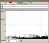
Digital-Zero Remain Noise (BW 96kHz)

Sampling-Rate 44.1k File Playback

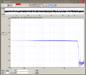
Sampling-Rate 96k File Playback
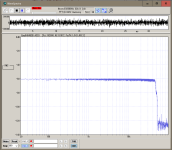
Sampling-Rate 192k File Playback
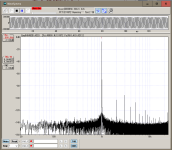
44.1k 16bit SinWave Playback
Selfboot is not ready, but the on-the-fly configuration is working...
Quick check Result2: Raspberry-Pi to Output Channel 8 (DAC fs=96kHz)
The board was placed in the open space. Wall-power supply adaptor was used. So the shielding and GND line connection is not optimized yet.
Digital-Zero Remain Noise (BW 24kHz)

Digital-Zero Remain Noise (BW 96kHz)

Sampling-Rate 44.1k File Playback

Sampling-Rate 96k File Playback

Sampling-Rate 192k File Playback

44.1k 16bit SinWave Playback

Last edited:
Hello there,
I joined the party a bit late.
Still, the project looks amazing and ticks all the right boxes. Good job so far CyberPit.
One thing came to my mind for all who want to integrate the PCB into a bigger case like an 19" rack case. Maybe one can have an additional assembly where there are pin headers (or some other kinf of connector) for the potentiometers/switches/encoders (basically all the things on one side of the PCB) to be able to connect wires and have them mounted onto the case.
@CyberPit Also I am happy to contribute to the project. So if there is a way I can support you, let me know.
Ludwig
Member
Joined 2018
Hello Ludwing-San,
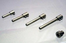
Another idea is to replace the onboard pots with 2.54mm pin header-pins or connectors.
Also, the toggle switches can be replaced with 2.54mm pitch header pins for wire connection. I guess extending LED light with optical fiber is not easy, so I would like to add extension header pin lands for the next version PCB design.
Thanks for giving me comments.
CyberPit
It's my pleasure to involve the community. Many thanks who gave me comments, suggestions, requests, and cheers.@CyberPit Also I am happy to contribute to the project. So if there is a way I can support you, let me know.
Well, I also think about the same thing. One idea for extending potentiometer shafts is something like this...One thing came to my mind for all who want to integrate the PCB into a bigger case like an 19" rack case. Maybe one can have an additional assembly where there are pin headers (or some other kinf of connector) for the potentiometers/switches/encoders (basically all the things on one side of the PCB) to be able to connect wires and have them mounted onto the case.

Another idea is to replace the onboard pots with 2.54mm pin header-pins or connectors.
Also, the toggle switches can be replaced with 2.54mm pitch header pins for wire connection. I guess extending LED light with optical fiber is not easy, so I would like to add extension header pin lands for the next version PCB design.
Thanks for giving me comments.
CyberPit
Member
Joined 2018
Today, I replaced SPI EEPROM with 25LC1024. But the result was not changed.
So I create a new SigmaStudio project again, then the EEPROM writing action works successfully.
I guess the project file had something wrong. The new file works great and the board can boot from the EEPROM!
I'll try M95256-RMN6TP later.
Anyway, now I can concentrate on developing the application. 🎉
CyberPit
So I create a new SigmaStudio project again, then the EEPROM writing action works successfully.
I guess the project file had something wrong. The new file works great and the board can boot from the EEPROM!
I'll try M95256-RMN6TP later.
Anyway, now I can concentrate on developing the application. 🎉

CyberPit
Wonderful news!
I would say this is the more flexible/versatile solution compared to extending the potentiometer shafts. 2x3 pin headers or box headers might already fit the footprint of the pots.Another idea is to replace the onboard pots with 2.54mm pin header-pins or connectors.
Sounds great.I guess extending LED light with optical fiber is not easy, so I would like to add extension header pin lands for the next version PCB design.
Hello Pit.Hello Ludwing-San,
It's my pleasure to involve the community. Many thanks who gave me comments, suggestions, requests, and cheers.
Well, I also think about the same thing. One idea for extending potentiometer shafts is something like this...
View attachment 1168272
Another idea is to replace the onboard pots with 2.54mm pin header-pins or connectors.
Also, the toggle switches can be replaced with 2.54mm pitch header pins for wire connection. I guess extending LED light with optical fiber is not easy, so I would like to add extension header pin lands for the next version PCB design.
Thanks for giving me comments.
CyberPit
Having header pins on the pcb should make the istallation very flexible i suppose.
Maurizio.
Member
Joined 2018
Thank you, everyone.
Today I established workarounds against all the issues.
https://github.com/freeDSP/freeDSP-OCTAVIA/wiki/Errata-and-Workarounds
All the input works as I expected. Other news was using 256kbit EEPROM M95256.
The EEPROM properties setting should be set as follows...

Now the board can boot from the onboard M95256 EEPROM.
I will commit the sample project files in a few days...
CyberPIt
Today I established workarounds against all the issues.
https://github.com/freeDSP/freeDSP-OCTAVIA/wiki/Errata-and-Workarounds
All the input works as I expected. Other news was using 256kbit EEPROM M95256.
The EEPROM properties setting should be set as follows...
Now the board can boot from the onboard M95256 EEPROM.
I will commit the sample project files in a few days...
CyberPIt
Member
Joined 2018
An example of the 3way Channel Divider SigmaStudio project had been uploaded.
FreeDSP OCTAVIA Git-Hub Page
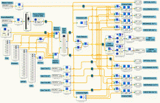
Enjoy DIY Audio Activities!
CyberPit
FreeDSP OCTAVIA Git-Hub Page

Enjoy DIY Audio Activities!
CyberPit
Hello Pit.
Great Job..!! The changes reported on the web page will implemented on the oard design as well?
ciao.
Great Job..!! The changes reported on the web page will implemented on the oard design as well?
ciao.
Member
Joined 2018
Okay, I will upload Symbols and Footprints later.
Now I'm making the
case as well...
Now I'm making the
case as well...
Hi CyberPit,
looking really good so far.
Is there something to keep in mind when choosing a power supply and do you have an estimate how much power the board draws?
I had in mind to put an open frame or enclosed MeanWell PSU in the case together with the dsp or is this a bad idea?
Ludwig
looking really good so far.
Is there something to keep in mind when choosing a power supply and do you have an estimate how much power the board draws?
I had in mind to put an open frame or enclosed MeanWell PSU in the case together with the dsp or is this a bad idea?
Ludwig
Member
Joined 2018
The milling takes more than 5 hours ... 
Some errors occur. Anyway, now I'm ready for the final build...
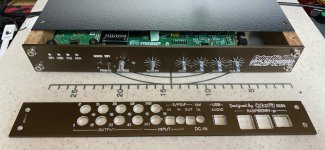
I will measure the actual consumption current later.
CyberPit

Some errors occur. Anyway, now I'm ready for the final build...

Well, now I'm thinking about changing the wall power adaptor to 9V to reduce the power of heat.Is there something to keep in mind when choosing a power supply and do you have an estimate how much power the board draws?
I will measure the actual consumption current later.
It's a good idea to make a product for all in one design. You should care about the EMC and Magnetic noise from the Power supply unit. On the other hand, most wall power adaptors are noisy power sources as well.🤔I had in mind to put an open frame or enclosed MeanWell PSU in the case together with the dsp or is this a bad idea?
CyberPit
Last edited:
- Home
- Source & Line
- Digital Line Level
- FreeDSP OCTAVIA