Member
Joined 2018
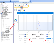
I'm stuck on designing a Linkwitz-Reiley 8th order crossover. Simulating in SigmaStudio, 4th order crossover is perfect as below...
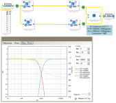
But just cascading the same one, the phase is perfectly matched, but the crossover point would be a -6dB dip in total system response.
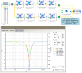
So I try to move the cut-off frequency toward the crossover frequency.
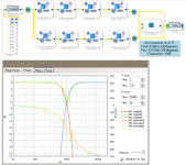
The total frequency response has a -7.5dB dip. This is worse than before!
Does anyone know how to solve this problem?
CyberPit

But just cascading the same one, the phase is perfectly matched, but the crossover point would be a -6dB dip in total system response.

So I try to move the cut-off frequency toward the crossover frequency.

The total frequency response has a -7.5dB dip. This is worse than before!
Does anyone know how to solve this problem?
CyberPit
Last edited:
Member
Joined 2018
uriy-ch-San,
Fixed crossover frequency is inconvenient in the case of cut-and-try speaker tuning.So, I just want to build a voltage-selectable variable crossover-frequency dividing network.
Current implementation is like this...
I believe L-R8 filtering is possible because you suggested an example.
CyberPit
Last edited:
LR crossovers are built from Butterworth crossovers of half the LR order, not Linkwitz-Rileys. For example, LR4 is composed of two B2s in cascade. So for creating an LR8 you would cascade two 4th order Butterworth filters, not LR4s.
Remember LR transfer functions are 6 dB down at the crossover frequency, so two of them in series means the xovr point is 12 dB down, as you saw. Compare this with Butterworth filters being 3 dB down so cascading two of those yields the desired 6dB down at crossover.
Remember LR transfer functions are 6 dB down at the crossover frequency, so two of them in series means the xovr point is 12 dB down, as you saw. Compare this with Butterworth filters being 3 dB down so cascading two of those yields the desired 6dB down at crossover.
https://www.linkwitzlab.com/filters.htm
Its a table at the site with the Q values needed for the 2. order filters
From the horse mouth;-)
Its a table at the site with the Q values needed for the 2. order filters
From the horse mouth;-)
Member
Joined 2018
Thanks, DSP-Geek-San and torgeirs-San
The inventor says each stage Q equals 0.54, 1.34, 0.54, 1.34
So I put into those values...
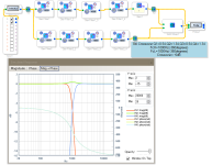
Not bad. But there is +0.5dB peak. I thought this might be some fraction errors.
So I spread the crossover frequency a little...
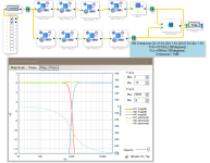
It's almost a flat response. I guess this will be enough for actual use.
Thank you guys, now I can update my design.
CyberPit


The inventor says each stage Q equals 0.54, 1.34, 0.54, 1.34
So I put into those values...

Not bad. But there is +0.5dB peak. I thought this might be some fraction errors.
So I spread the crossover frequency a little...

It's almost a flat response. I guess this will be enough for actual use.
Thank you guys, now I can update my design.
CyberPit

Member
Joined 2018
Member
Joined 2018
A special thanks to Mir. Linkwitz. And forum members who supported me.
Now I can build an LR8 Channel Divider, which has a tunable Crossover frequency. At the center position of the pots, the frequency response was measured.

(Please ignore the noises below 500Hz. It depends on my measurement system.)
Git-hub Wiki
CyberPit
Now I can build an LR8 Channel Divider, which has a tunable Crossover frequency. At the center position of the pots, the frequency response was measured.
(Please ignore the noises below 500Hz. It depends on my measurement system.)
Git-hub Wiki
CyberPit
Last edited:
A joy to spread the word of late mr Linkwitz.
You have implemented the classic Behringer dcx9624 feature for adjusting filter freq. Really handy.
Regarding the LR filter the importance of the phase is often understated
LR has 3 requirements. 2 of them are phase related
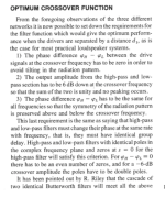
https://www.linkwitzlab.com/JAES/jaes_papers76.htm
You have implemented the classic Behringer dcx9624 feature for adjusting filter freq. Really handy.
Regarding the LR filter the importance of the phase is often understated
LR has 3 requirements. 2 of them are phase related

https://www.linkwitzlab.com/JAES/jaes_papers76.htm
Yeah, that's cool. I didn't have the strength and desire to implement the functions of changing the crossover frequency in Sigma Studio. By the way, I found an inaccuracy, you output the left channel in place of the right channel in spdif, maybe this is what you need or it's just a small mistake.Now I can build an LR8 Channel Divider, which has a tunable Crossover frequency.
Member
Joined 2018
Uriy-ch-San,
Maybe it depends on AUX-ADC noise, I checked the Full-Range output with the sine wave. The ourput spectrum was like this...
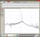
An extremely high-level spread noise floor existed. And it comes from the Volume blocks. This AM nose disappeared when I changed the CV to a DC source.
So I try to put various LPF blocks after the AUX-ADC input. But most of the LPF blocks do not pass DC.
Finally, I found the First Order Filter Block passes DC. It works fine as I expected. The value is stabilized very well.
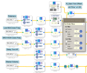
After this modification, the output spectrum is changed drastically.
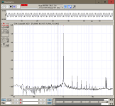
The output became very clean as I expected. This modification was applied to Balance and delay control.
Now you can clone the latest SigmaStudio project from the GitHub page.
https://github.com/freeDSP/freeDSP-...Balance_Sweep-Cross_TW-Delay_Improvrd.dspproj
CyberPit
Maybe it depends on AUX-ADC noise, I checked the Full-Range output with the sine wave. The ourput spectrum was like this...

An extremely high-level spread noise floor existed. And it comes from the Volume blocks. This AM nose disappeared when I changed the CV to a DC source.
So I try to put various LPF blocks after the AUX-ADC input. But most of the LPF blocks do not pass DC.
Finally, I found the First Order Filter Block passes DC. It works fine as I expected. The value is stabilized very well.

After this modification, the output spectrum is changed drastically.

The output became very clean as I expected. This modification was applied to Balance and delay control.
Now you can clone the latest SigmaStudio project from the GitHub page.
https://github.com/freeDSP/freeDSP-...Balance_Sweep-Cross_TW-Delay_Improvrd.dspproj
CyberPit
Last edited:
- Home
- Source & Line
- Digital Line Level
- FreeDSP OCTAVIA
