Hi CyberPit-San,
I'll look for a suitable 220µF cap then. What do you think, should we move C13 and change the footprint before we do the group buy?
Ludwig
That makes sense, thanks for clarifying.Well, To prevent the heat physically, I needed a long leaded capacitor. That was the only one I have at that time.
No other meaning of choice. The board should have a bigger footprint and be away from the heat source.
I'll look for a suitable 220µF cap then. What do you think, should we move C13 and change the footprint before we do the group buy?
Ludwig
Member
Joined 2018
Ludwing_San,
Today I found one more mistake on J13. The Anode side power (+5V) is connected to the same power rail of RPI. So the source position LED is not turned on when the RPI is not active. And one of the worse things is it's too bright😎
The workaround for this is to connect the Source Indicator LED's Anodes to pin6 of J3. (+3.3V)

This is the biggest mistake in this initial version 0.1😱
Can you wait or not?
Regards,
CyberPit
Today I found one more mistake on J13. The Anode side power (+5V) is connected to the same power rail of RPI. So the source position LED is not turned on when the RPI is not active. And one of the worse things is it's too bright😎
The workaround for this is to connect the Source Indicator LED's Anodes to pin6 of J3. (+3.3V)
This is the biggest mistake in this initial version 0.1😱
I want to fix the current issues, but it will take one week. I'll prepare the new PCBA Data if you can wait a week.I'll look for a suitable 220µF cap then. What do you think, should we move C13 and change the footprint before we do the group buy?
Can you wait or not?
Regards,
CyberPit
Hello everyone! I noticed this project, which conveniently uses a Raspberry Pi, connected via SPI/I2C to a SigmaDSP device.
I made a software package to use SigmaStudio over TCP with the Raspberry Pi as a programmer. So you don't need the USBi programmer, and can debug/test over Ethernet.
Find it here: https://github.com/blus-audio/sigmadsp
I hope you find it useful.
I made a software package to use SigmaStudio over TCP with the Raspberry Pi as a programmer. So you don't need the USBi programmer, and can debug/test over Ethernet.
Find it here: https://github.com/blus-audio/sigmadsp
I hope you find it useful.

Hi CyberPit-San,
Thats unfortunate, but a complex design without a mistake is like winning a lottery 😆
But so far I would say these are all very minor mistakes. So you still did a very good job 👍
Maybe you can also integrate the header for the status LED while fixing the other issues?
Something I also noticed while searching for the THT components: You use this small tactile switch, which is angled and only has two pins. This version is almost impossible to source over here. And if you find it somewhere it is over 1USD per peace. All the right angle tactile switches I see have some supporting pins like in the picture below. Do you have a footprint for those switches as well? I mean we could also cut the rear legs of the switch...
Ludwig

Thats unfortunate, but a complex design without a mistake is like winning a lottery 😆
But so far I would say these are all very minor mistakes. So you still did a very good job 👍
Yes, I think we can wait. I am also not quite done with searching all the components and the final pricing for the group buy. Especially the input indicator is probably something that most of us want to use, so its good if you don't need sunglases while the DSP is in use 😆.Can you wait or not?
Maybe you can also integrate the header for the status LED while fixing the other issues?
Something I also noticed while searching for the THT components: You use this small tactile switch, which is angled and only has two pins. This version is almost impossible to source over here. And if you find it somewhere it is over 1USD per peace. All the right angle tactile switches I see have some supporting pins like in the picture below. Do you have a footprint for those switches as well? I mean we could also cut the rear legs of the switch...
Ludwig
This sounds very good and will definitly come in handy.I made a software package to use SigmaStudio over TCP with the Raspberry Pi as a programmer.
I also have the intention to misuse the USBi connector on the board.
My plan is to connect a microcontroller that reads out registers of the ADAU chip and displays thinks like the selected input, volumes, etc on an OLED display, which I want to integrate into the case. I will definitly keep you updated on the implementation if you are interested.
Sure why not!I will definitly keep you updated on the implementation if you are interested.
For testing, you can also start with my tool on the Raspberry Pi. It allows arbitrary register reads. It can also parse SigmaStudio parameter files and detect volume cells automatically (if they follow a certain naming scheme). You can then adjust volume with a command-line tool.
For your register readout, keep in mind that addresses change, when you change blocks in the SigmaStudio configuration file. This is especially important, if you want to write to a register.
For that reason, I usually keep a DC cell with a certain value in my application as a form of "checksum". I try to read it from the DSP on startup and only allow register accesses, if the readout matches the expected value.
Very nice project @CyberPit! Do you know what will be estimated cost for 1 board? Other variants planned? For example without dacs, just i2s exposed to connect own dac(or this one split into 2 boards)?
Its possible to control dsp over spi/i2c? For example add multplexer control in sigmastudio and control it over i2c/spi with external mcu? Or all needs to be done via USBi?
Thought its possible by spi/i2c registers, but I guess not?This sounds very good and will definitly come in handy.
I also have the intention to misuse the USBi connector on the board.
My plan is to connect a microcontroller that reads out registers of the ADAU chip and displays thinks like the selected input, volumes, etc on an OLED display, which I want to integrate into the case. I will definitly keep you updated on the implementation if you are interested.
Its possible to control dsp over spi/i2c? For example add multplexer control in sigmastudio and control it over i2c/spi with external mcu? Or all needs to be done via USBi?
Yes, you have full register access over SPI/I2C. The USBi interface does nothing else.Its possible to control dsp over spi/i2c
So DSP<--i2c-->USBi<-->MCU -sure
DSP<--i2c-->MCU -wont work? I mean old fashioned way, how you control dac for example
DSP<--i2c-->MCU -wont work? I mean old fashioned way, how you control dac for example
The USBi device is a USB to I2C/SPI bridge with a special firmware that communicates with SigmaStudio.
The protocol for communication between the USBi and the DSP is open and you can thus replicate it on any other hardware.
You can use a microcontroller or other hardware with SPI/I2C to directly communicate with the DSP - no USBi required in that case.
The protocol for communication between the USBi and the DSP is open and you can thus replicate it on any other hardware.
You can use a microcontroller or other hardware with SPI/I2C to directly communicate with the DSP - no USBi required in that case.
USBi is just a SPI/I2C connection. So everytthing you can do via USB, you can do with MCU as well. So yes, you can configure multiplexer in Sigma Studio and switch them via MCU.
One board will be about 100-120 USD from my rough estimation at the moment. A more precise price will come in the next days.Do you know what will be estimated cost for 1 board?
That's a good idea!For that reason, I usually keep a DC cell with a certain value in my application as a form of "checksum"
Last edited:
Dear Cyber Pit - San good morning .
You made a great job around this DSP development..this is a really minor problem considering all your big effort aroud it.
Yes of course we can wait one week or more. Take your time to do it.
Have a good day.!!!
Maurizio
You made a great job around this DSP development..this is a really minor problem considering all your big effort aroud it.
Yes of course we can wait one week or more. Take your time to do it.
Have a good day.!!!
Maurizio
Cyberpit-Sensei, This tickles my brain really hard. I'm curious what the end result will cost-- send-cut-send PCB and BOM included. This site's eyes are on you, and we can't wait to see what you deliver. I'm sure this will be a fun summer project, and I hope I get the chance to build one after a few iterations and tests.
EDIT: DUH you already said like, $100 per unit. NICE!
EDIT: DUH you already said like, $100 per unit. NICE!
Last edited:
Sorry to crush your dreams, but 100USD will unfortunately not be possible...EDIT: DUH you already said like, $100 per unit. NICE!
Those THT components add up a bit and I may have to pay customs/taxes for the JLC order 😢
I am almost done, Tomorrow or on Friday i will have a price for you with everything included. We can then also personalize a bit, like if you want the RCA sockets even if its a balanced board (if not you can save already 11$) or do you want long or short pots or get them yourself, ...
Ludwig
Member
Joined 2018
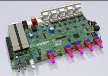
Almost there...

CyberPit
- Fixed previous issues
- Add headers for LED
- Change Push switch
- Move DSP Reset button
- Heat-spreader for U3/U7
- Add GNDA Land
- Change Mute control logic for USB Input
CyberPit
Member
Joined 2018
elagil-San,
Thank you very much.
Ludwig-San,
ThePOWER/STATUS indicator LED had moved between the MAINS and RPI-POWER switches. This change comes from making space for an external RGB-LED connection header.
I fixed a mute control feature of Combo384 to PCM502A's XSMT. Additional some parts were needed for this change. Please include them for the precise cost estimation.
Best Regards to all,
CyberPit
I made a software package to use SigmaStudio over TCP with the Raspberry Pi as a programmer. So you don't need the USBi programmer, and can debug/test over Ethernet.
Great! That's what I wanted to realize in this project. I will study your suggested reference sources.For testing, you can also start with my tool on the Raspberry Pi. It allows arbitrary register reads. It can also parse SigmaStudio parameter files and detect volume cells automatically (if they follow a certain naming scheme). You can then adjust volume with a command-line tool.
Thank you very much.
Ludwig-San,
I changed that tactile switch, but the space was insufficient for two switches. So I moved the "DSP-RESET" switch to the side of USBi connector. According to the TCP USBi support, the possibility of the use of USBi will decrease later in this project. Previously I implemented a GPIO connection jumper JP3 for the remote DSP-RESET feature. As a result of this, The shutdown/reboot/restart button remains in the middle of the MASTER volume and AUX1 POT.All the right angle tactile switches I see have some supporting pins like in the picture below. Do you have a footprint for those switches as well? I mean we could also cut the rear legs of the switch...
ThePOWER/STATUS indicator LED had moved between the MAINS and RPI-POWER switches. This change comes from making space for an external RGB-LED connection header.
I fixed a mute control feature of Combo384 to PCM502A's XSMT. Additional some parts were needed for this change. Please include them for the precise cost estimation.
Best Regards to all,
CyberPit
Attachments
CyberPit-San,
For everyone who wants to get a better idea of the price. Without the new changes, for 5 boards, I calculated 141.62€ ( 154.37$). This includes the unbalanced RCA sockets, which can be left out. If I am lucky and I dont have to pay import sales tax fot the JLC order i gets around 14 € cheaper, but don't count on that.
Ludwig
That makes it much easiert to find suitable switches, thanks alot.I changed that tactile switch
Thats ok, I just need access to the I2C bus which is also possible vie the optional Display header.According to the TCP USBi support, the possibility of the use of USBi will decrease later in this project.
I justed wanted to post my price calculations when I read your post. I guess I will wait until you are done with all the changes so I can get a new price for the JLC PCBA.Additional some parts were needed for this change. Please include them for the precise cost estimation.
For everyone who wants to get a better idea of the price. Without the new changes, for 5 boards, I calculated 141.62€ ( 154.37$). This includes the unbalanced RCA sockets, which can be left out. If I am lucky and I dont have to pay import sales tax fot the JLC order i gets around 14 € cheaper, but don't count on that.
Ludwig
Member
Joined 2018
Hello Guys,
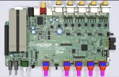
Today, I released the design of FreeDSP OCTAVIA version 0.2.
All the information and design data will be available following the Git-Hub page.
https://github.com/freeDSP/freeDSP-OCTAVIA
I tried to self-check my design many times, but If you noticed errors, please let me know the issues.
Enjoy DIY Activities!
CyberPit
Attachments


Hello,
Now here are some numbers for version 0.2.
So far 5 people are interested in a balanced board and 2 are interested in the unbalanced version, but they are fine with the balanced one as well.
So I calculated for different numbers of boards the prices:

Note1: The 7 boards is PCBA with 5 boards assambled and PCB with 2 boards assembled. Thats why it is more expensive per board as the 5 board version...
Note2: I shifted the componentes between mouser and digikey a bit to reach free shipping. Thats why some numbers seem wierd between different board numbers.
Note3: The price includes 5 stereo RCA jacks, 4 of them are not needed for the balanced version. Here the question is, if you still want them in case you want to change your board to a different version. I would handle this decission individually. So it gets cheaper by a few dollards if you want to leave them out.
Note4: There will be an additional shipping cost from me to you that depends on your country. If your are far away from Germany you might get cheaper if you find someone else in your are who is interested as shipping cost gets very high. If I remember correctly Germany to Australia was something like 40-50 EUR.
In the next days I will probably reach out to every one of you to check your individuals needs.
I will also calculate the price for 2 unbalanced boards, but for that I have to create a different BOM, so bear with me on this one...
Have a lovely end of the weekend or a good day if the weekend is already over 😉
Ludwig
Thanks CyberPit for resolving all the isues in this short time!Today, I released the design of FreeDSP OCTAVIA version 0.2.
Now here are some numbers for version 0.2.
So far 5 people are interested in a balanced board and 2 are interested in the unbalanced version, but they are fine with the balanced one as well.
So I calculated for different numbers of boards the prices:
Note1: The 7 boards is PCBA with 5 boards assambled and PCB with 2 boards assembled. Thats why it is more expensive per board as the 5 board version...
Note2: I shifted the componentes between mouser and digikey a bit to reach free shipping. Thats why some numbers seem wierd between different board numbers.
Note3: The price includes 5 stereo RCA jacks, 4 of them are not needed for the balanced version. Here the question is, if you still want them in case you want to change your board to a different version. I would handle this decission individually. So it gets cheaper by a few dollards if you want to leave them out.
Note4: There will be an additional shipping cost from me to you that depends on your country. If your are far away from Germany you might get cheaper if you find someone else in your are who is interested as shipping cost gets very high. If I remember correctly Germany to Australia was something like 40-50 EUR.
In the next days I will probably reach out to every one of you to check your individuals needs.
I will also calculate the price for 2 unbalanced boards, but for that I have to create a different BOM, so bear with me on this one...
Have a lovely end of the weekend or a good day if the weekend is already over 😉
Ludwig
- Home
- Source & Line
- Digital Line Level
- FreeDSP OCTAVIA