Hello everyone,
just to prevent missunderstaning, I have not inlcuded the Amanero Combo384 USB module as it is rather optional and not everyone might need/want it. I suppose If you want one with your group and it is hard for you to source one, we can work something out.
Ludwig
just to prevent missunderstaning, I have not inlcuded the Amanero Combo384 USB module as it is rather optional and not everyone might need/want it. I suppose If you want one with your group and it is hard for you to source one, we can work something out.
Alright JMF, no problem.I finally won't participate. This is a great project, and the price is very competitive, but probably I won't have sufficient usage for it.
Sorry for the change. All the best for the next phase.
Ludwig

Hi Ludwig. I'm interested in joining your group buy. Many thanks for organising this. If I understand correctly the balanced version can be modified fairly simply to run with unbalanced outputs. If so, I'd be interested in the balanced board and will convert it. I'll probably need balanced at a later date, so the option to switch back will be useful. If I've misunderstood please let me know.
Many thanks to CyberPit for sharing this design!
Many thanks to CyberPit for sharing this design!
Hi Captain B,
yes you can convert it. You have to remove some resistors, replace some with 0 Ohm and add some jumpers. The Opamps and the transitors can stay in palce if I am not mistaken.
Ludwig
yes you can convert it. You have to remove some resistors, replace some with 0 Ohm and add some jumpers. The Opamps and the transitors can stay in palce if I am not mistaken.
Ludwig
Member
Joined 2018
Hi Ludwig-San,
Well, it runs in stable.I run it all day long with Raspberry-pi Net-Radio Streaming with 2way Crossover.
In Japan, more than 90% of Audio equipment is Class-II (doesn't have a GND pin receptacle)
So I guess it will be nice to have an Earth-Terminal on Chassis. Because I'm using a differential output version, so sometimes I needed to connect each chassis. ( To limit the difference voltage within the power rail.)
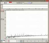
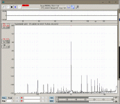
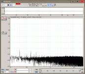
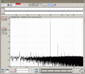
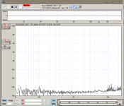
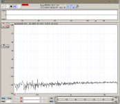
I measured some Audio performances...
If I turn on the Raspbery-pi, the ADC remaining noise will increases by 2dB.
CyberPit
Well, it runs in stable.I run it all day long with Raspberry-pi Net-Radio Streaming with 2way Crossover.
In Japan, more than 90% of Audio equipment is Class-II (doesn't have a GND pin receptacle)
So I guess it will be nice to have an Earth-Terminal on Chassis. Because I'm using a differential output version, so sometimes I needed to connect each chassis. ( To limit the difference voltage within the power rail.)
I measured some Audio performances...
If I turn on the Raspbery-pi, the ADC remaining noise will increases by 2dB.
CyberPit
Attachments
-
 Optical_RemainNoise_BW22k.GIF76.2 KB · Views: 117
 -
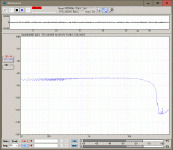
 Optical_FreqResp_48kHz.GIF78.4 KB · Views: 118
 -
 Optical_FreqResp_96kHz.GIF78.2 KB · Views: 104
 -
 Optical_FreqResp_192kHz.GIF78.5 KB · Views: 116
 -
 SPDIF_Distortion_OPT.GIF79.4 KB · Views: 113
 -
 ADC_RemainNoise_R.GIF78.7 KB · Views: 126
 -
 ADC_DIstortion_-20dB_R.GIF83.4 KB · Views: 114
 -
 ADC_DIstortion_-10dB_R.GIF84 KB · Views: 116
 -
 ADC_DIstortion_0dB_L.GIF86.4 KB · Views: 112
 -
 ADC_FreqResp_BW96k.GIF79.8 KB · Views: 115
Last edited:
Hi CyberPit-San,
Thanks for your feedback and the measurements. I was wondering why are the THD numbers on the optical spdif worse compared to the pi playback measurements you posted a while ago? Spdif is purely digital so it should be very similar or am I wrong? Can you enlighten me?
What is your take on the measurements? It is always a bit tough for me to differentiate between the race to better and better THD numbers in the audio industry and how much you will really notice.
Ludwig
Member
Joined 2018
Member
Joined 2018
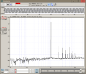
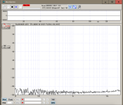
Currently, my OCTAVIA board configuration is Differential-Output. It needs to connect the signal source and target chassis to each other. So I changed the GND connection points between OCTAVIA and Measurement devices. Also, I update the USB Audio Interface driver.
The measurement result is changed...
My USB Audio Interface has some performance problems with the large input level. Just check the output level for @0db
CyberPit
The measurement result is changed...
My USB Audio Interface has some performance problems with the large input level. Just check the output level for @0db
CyberPit
Attachments


Last edited:
Hi CyberPit-San,
that is quite the difference. Thanks for the effort I imagine the ADC results would look better now as well.
Ludwig
that is quite the difference. Thanks for the effort I imagine the ADC results would look better now as well.
Ludwig
Member
Joined 2018
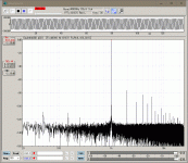
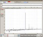
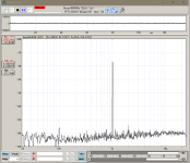
Here's the measured data update
ADC Analog Input
The results were not so much different. Because it's close to a single-end input ADC PCM1808 performance limit.
ADC Analog Input
The results were not so much different. Because it's close to a single-end input ADC PCM1808 performance limit.
Attachments
Member
Joined 2018
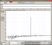
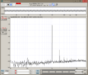
Also the USB input
Maybe my USB Audio Interface has some performance problems with the large input level. It looks always the same...
Maybe my USB Audio Interface has some performance problems with the large input level. It looks always the same...
Attachments
Member
Joined 2018
Finally the Raspberry-pi
Attachments
-
 RPi_Distortion_-10dB@48k.png196.3 KB · Views: 96
 -
 RPi_DIstortion_-20dB@48k.png31.3 KB · Views: 98
 -
 RPi_DigitalZeroPlayback@48k.png29.4 KB · Views: 88
 -
 RPi_PlayStopRemainNoise.png29 KB · Views: 88
 -
 RPi_Distortion_0dB@48k.png32.3 KB · Views: 89
 -
 RPi_FrequencyResponse_44k1.png30.2 KB · Views: 103
 -
 RPi_FrequencyResponse_96k.png31.5 KB · Views: 91
 -
 RPi_FrequencyResposer_192k.png31.2 KB · Views: 86
Hi CyberPit-San,
thank you very much for all the measuements and therefore your time you put into this.
If the group buy is done I could make some measurements as well and see if there is any difference on my side. Or if you have an other DAC laying around you could check if you measure something similiar than we know if it is the USB interface or not.
Just to be clear, I don't want to sound negative or want you to get the impression that I talk bad about your results. Your work is amazing, no doubt. I just want to openly analzse the results., I guess this is the engineer in me, hunting for perfection 😉
Ludwig
thank you very much for all the measuements and therefore your time you put into this.
I mean it is to be expected that there is not much difference between all the digital inputs. In all cases we measure basically the performance of the DAC (and of your USB audio interface). But I was also wondering why the harmonics are so much higher at large input levels. If you look at the DACs datasheet there is an increase close to 0dbfs but not that much. It could be your usb interface, i could be something else.Maybe my USB Audio Interface has some performance problems with the large input level. It looks always the same...
If the group buy is done I could make some measurements as well and see if there is any difference on my side. Or if you have an other DAC laying around you could check if you measure something similiar than we know if it is the USB interface or not.
Just to be clear, I don't want to sound negative or want you to get the impression that I talk bad about your results. Your work is amazing, no doubt. I just want to openly analzse the results., I guess this is the engineer in me, hunting for perfection 😉
Ludwig
Indeed! To echo Ludwig's remarks it is incredible to see the Octavia board come this far in such a short time. Huge thanks to CyberPit-San for sharing this with the DIY community. To already have a working board, with openly shared measurements to help chase further performance refinements - it's all just very impressive and admirable 👏 🙂Your work is amazing, no doubt. I just want to openly analzse the results
Member
Joined 2018
Thanks, Ludilu-San, rrobot-San, and many others who responded to this thread.
Well, I'm very carefully designed this PCB to keep the analog signals clean from DIgital device-oriented noises. The audio noise floors are almost clean and flat as I expected. 😎
On the other hand, the large signal distortion could not be so much care at this time. I believe community members will improve that point in the near future.😉
It may require some routing/value change and/or the use of expensive film capacitors for the audio path. Anyway, I look forward to future developments in this community.
Best Regards,
CyberPit
Hello again everyone,
so as agreed with all of you, who are interested in the group buy, individually, I will know order a board in the next couple of days to have a look at the situation with the harmonics. Once this is solved, we proceed with the group order.
So I'd like to start a little brainstorming of possible causes and things to test to find the cause. So here is a list of what I came up with so far, feel free to comment on the points or maybe bring in some new ideas.
Things I want to measure and try:
Now I am happy to hear your thoughts 🙂
Ludwig
so as agreed with all of you, who are interested in the group buy, individually, I will know order a board in the next couple of days to have a look at the situation with the harmonics. Once this is solved, we proceed with the group order.
So I'd like to start a little brainstorming of possible causes and things to test to find the cause. So here is a list of what I came up with so far, feel free to comment on the points or maybe bring in some new ideas.
Things I want to measure and try:
- measure Board as it is with audio interface and oscilloscope -> to see wether it is a board issue or a measurement issue
- Board withoout mute mute transistors -> is it the transistors
- Board without the opamps -> is it the differential opamp circuit
- If this present now change C99 (other types like film capacitors should have less voltage dependent distortion, different size can also help)
- C99 and R124 is a low pass filter. The values used here are different compared to the datasheet, so other cut off frequency and other load on the DAC,
@CyberPit maybe you can tell me what the idea behind those values were? less resitance for better noise characteristic? - If the above measurements show that the opamp circuit is the culprit than different values on R132/R136 and R133/R137 might be worth a shot.
- if all the above did not improve the situation I would make a small PCB with just an output stage (DAC, opamp, mute circuit) with a routing focused on less distortion (probably 4 layer PCB) to test it in a cheaper way the doing the entire board
Now I am happy to hear your thoughts 🙂
Ludwig
Member
Joined 2018
Hello Ludwig-San,
I just recommend a choice of cap type for C99 is C0G(Class-1) or film (such as ECHU. but it's expensive.)
One important thing, I found a big mistake in updating the footprint of RCA-Jack. It was locked so the wrong pin assignment was not fixed. I just updated Git-Hub repository. I hope it is in time for ordering of your PCB. Plus I changed the notice for the wall power adaptor voltage from "12V" to "6.5V - 9V".
Sorry too late!
CyberPit
The value of these is not so deep means, a lower cut-off frequency and higher load impedance might make a different result. This has some possibility. Currently, DSP is running at 96kHz so the cut-off frequency can be down to half of the sample datasheet schematic of TI. (ex. 470R + 4.7nF)C99 and R124 is a low pass filter. The values used here are different compared to the datasheet, so other cut off frequency and other load on the DAC,
I just recommend a choice of cap type for C99 is C0G(Class-1) or film (such as ECHU. but it's expensive.)
One important thing, I found a big mistake in updating the footprint of RCA-Jack. It was locked so the wrong pin assignment was not fixed. I just updated Git-Hub repository. I hope it is in time for ordering of your PCB. Plus I changed the notice for the wall power adaptor voltage from "12V" to "6.5V - 9V".
Sorry too late!
CyberPit
Last edited:
Hello CyberPit-San,
Thank you for the input. I will try different values on the RC filter and also different types of caps.
BR
Ludwig
Thank you for the input. I will try different values on the RC filter and also different types of caps.
I have not ordered yet. Wanted to do it today. So all good. Thanks for the notice!One important thing, I found a big mistake in updating the footprint of RCA-Jack. It was locked so the wrong pin assignment was not fixed. I just updated Git-Hub repository. I hope it is in time for ordering of your PCB. Plus I changed the notice for the wall power adaptor voltage from "12V" to "6.5V - 9V".
BR
Ludwig
Hello everyone,
here is a small update:
Debugging board and parts should arrive by the end of the week.
So maybe at the weekend or next week I can start with some measurements and tests.
BR Ludwig
here is a small update:
Debugging board and parts should arrive by the end of the week.
So maybe at the weekend or next week I can start with some measurements and tests.
BR Ludwig
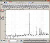
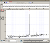
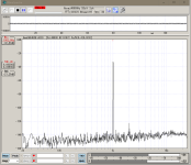
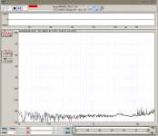
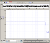
Alright,
first baseline masurement is in done. The numbers THD and THD-N look a bit better, but there is still room for improvement.

One thing is odd. I generated the sine wave on the dsp with the schematic below. I set the frequency to 1kHz but on the output I meaasure is 2 kHz. Has anyone an idea what might be the issue here ( I set up a new project since I am using the ADAU 1466) ?

Ludwig
first baseline masurement is in done. The numbers THD and THD-N look a bit better, but there is still room for improvement.
One thing is odd. I generated the sine wave on the dsp with the schematic below. I set the frequency to 1kHz but on the output I meaasure is 2 kHz. Has anyone an idea what might be the issue here ( I set up a new project since I am using the ADAU 1466) ?
Ludwig
- Home
- Source & Line
- Digital Line Level
- FreeDSP OCTAVIA