Hello! I don't know how to program, and I'm using minidsp SHD STUDIO to do room correction, and the sound is okay. But there is a fatal problem that the delay is very large, and the delay is obviously felt when playing virtual instruments. Is the total delay of freedsp operation large? I really want to learn freedsp to make a room processor by myself. Sorry, my English is not very good, most expressions are translated by Google, I hope you can understand
I think you will find that it is not the hardware that is causing the delay but what you are asking of it, room correction that involves phase or group delay adjustment ie using FIR filters will introduce throughput delay. The static hardware delay is typically 1-2ms.Hello! I don't know how to program, and I'm using minidsp SHD STUDIO to do room correction, and the sound is okay. But there is a fatal problem that the delay is very large, and the delay is obviously felt when playing virtual instruments. Is the total delay of freedsp operation large? I really want to learn freedsp to make a room processor by myself. Sorry, my English is not very good, most expressions are translated by Google, I hope you can understand
看看FIR用多少来决定最后的延迟就知道了?

English please. Rules:
Just look at how much FIR uses to determine the final delay?
Member
Joined 2018
Hi demoan-San,
I guess you are using FIR filter-based room correction. (Such as rephase, REW, etc...) It's a long-sized delay with the convolution method. So the delay(latency) comes from the algorithm itself. The latency will not change even If you change the hardware.
Sigma Studio supports MLSSA modeling and AutoEQ Wizard. (Also the FIR filtering)
Anyway. In your case, you need to change the room correction algorithm first.
CyberPIt
Member
Joined 2018
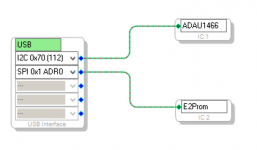
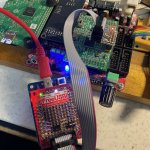
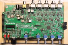
I made a small adaptor board that enables to change of the connection type from SPI to I2C.

A MW1466 daughter board which has USBi header for SPI connection was converted to USBi header with I2C connection. It needed to reboot after insetting this board.
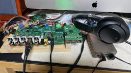
I could access the board and change the parameters of on-the-fly operation. Accessing speed was not so different from the SPI connection. (duration difference was within one second)
So I plan to change the USBi and R-Pi connection from SPI to I2C...
CyberPit
A MW1466 daughter board which has USBi header for SPI connection was converted to USBi header with I2C connection. It needed to reboot after insetting this board.
I could access the board and change the parameters of on-the-fly operation. Accessing speed was not so different from the SPI connection. (duration difference was within one second)
So I plan to change the USBi and R-Pi connection from SPI to I2C...
CyberPit
Attachments
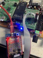

Good to see it actually works before implementing it on a new board integrating all the parts.
It's a cool setup you have, good for trying all the concepts of interfacing out.
Not sure I followed why you are going "back" to I2C for the programming part, if you are already using SPI?
Keeping the E2PROM on SPI makes a lot of sense as discussed to support large E2PROMs.
It's a cool setup you have, good for trying all the concepts of interfacing out.
Not sure I followed why you are going "back" to I2C for the programming part, if you are already using SPI?
Keeping the E2PROM on SPI makes a lot of sense as discussed to support large E2PROMs.
Member
Joined 2018
Hi Baldin-San,

The reading speed is not so different from I2C ...
SPI EEPROM is very rare in today's parts market. I'm completely stacked to choosing the boot ROM type selection.
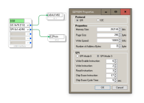
On the other hand, I'm considering changing the path USBi/R-pi to ADAU1452's slave port with I2C. This is not dought from the many reasons.
Pros:
CyberPit
Well, absolutely SPI is the best choice from the point of view of speed. So I would like to keep SPI connection between ADAU1452's master port to SPI EEPROM. But the actual 1466's accessing data rate was disappointed slowly as you can see.Not sure I followed why you are going "back" to I2C for the programming part, if you are already using SPI?
Keeping the E2PROM on SPI makes a lot of sense as discussed to support large E2PROMs.
The reading speed is not so different from I2C ...
SPI EEPROM is very rare in today's parts market. I'm completely stacked to choosing the boot ROM type selection.
On the other hand, I'm considering changing the path USBi/R-pi to ADAU1452's slave port with I2C. This is not dought from the many reasons.
Pros:
- No disadvantage in firmware writing duration.
- An possibility of reusing the software parts property of Aurora.
- Easy to implement the signal path switch between the R-Pi and USBi
- Easy to add a small display unit.
- Small possibility of electrical/magnetical noise from R-Pi
- I've never succeeded to find an example R-pi project I2C TCPi. (Help me please)
- Need more work 😱
CyberPit
Last edited:
Fully agree on the SPI E2PROM being the way to go. Still seem to be possible to get good and relatively cheap chips at Mouser.
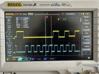
For the Programming, you have around 500 kHz clock (thought 1 MHz was the default).
Just dig measurements on the Wondom ICP3 programming interface which is running I2C.
I get ca 100 kHz on SCL line, so your SPI interface is in theory running 5 times faster. If it actually transfers data faster is of course a question, which will be dependent on the "overhead" of the protocol.
On my ADAU1701 boards I was protecting all the programming interface inputs by a series resistor of 470R and a 3.3V zenner diode.
Seeing that the voltages on the interface is actually only around 2.5V, this is not necessary, and the 470R will introduce a voltage drop which might cause the interface not to work properly.
On a USBi interface, can you be certain that the lines stays below 3.3V?
With you findings I will reconsider my choice of programming interface 😉
One question: On the ICP3 interface there are 2 extra lines WP (Write Protect) and RST (Reset). Are you using similar lines in your test for I2C? I would guess at least the RST needs to be connected to RST on the DSP chip ......
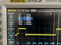
.... woou, I'm not used to using my oscilloscope in this way ... took me some time to make the right recordings while programming a ADAU1701 ..... and also looks like the scope could use a bit of cleaning 😉
For the Programming, you have around 500 kHz clock (thought 1 MHz was the default).
Just dig measurements on the Wondom ICP3 programming interface which is running I2C.
I get ca 100 kHz on SCL line, so your SPI interface is in theory running 5 times faster. If it actually transfers data faster is of course a question, which will be dependent on the "overhead" of the protocol.
On my ADAU1701 boards I was protecting all the programming interface inputs by a series resistor of 470R and a 3.3V zenner diode.
Seeing that the voltages on the interface is actually only around 2.5V, this is not necessary, and the 470R will introduce a voltage drop which might cause the interface not to work properly.
On a USBi interface, can you be certain that the lines stays below 3.3V?
With you findings I will reconsider my choice of programming interface 😉
One question: On the ICP3 interface there are 2 extra lines WP (Write Protect) and RST (Reset). Are you using similar lines in your test for I2C? I would guess at least the RST needs to be connected to RST on the DSP chip ......
.... woou, I'm not used to using my oscilloscope in this way ... took me some time to make the right recordings while programming a ADAU1701 ..... and also looks like the scope could use a bit of cleaning 😉
Attachments
Last edited:
Member
Joined 2018
Thanks for your experiment.
I also checked with my FreeDSP Catamaran A/B board. The result shows...
FreeUSBi configure to ADAU1701 (86.7k)

ADAU1701 SelfBoot from I2C E2PROM (381.7k)

Additionally, the MusicWorks MW1466 board with FreeUSB results is as follows...
FreeUSBi configure to ADAU1466 via I2C (86.7k)

FreeUSBi configure to ADAU1466 via SPI (365k)

ADAU1466 SelfBoot from SPI E2PROPM (476k)

According to the measurement information shows, the SPI and I2C self-boot data-rate difference is small.
But, SPI's data rate on-the-fly configuration and writing through USBi is almost 4 times faster than I2C.
Finally, the actual time duration for E2PROM programming has some overhead and something related to addressing/wait protocol makes a small difference between them.
The conclusion:
The difference is not too much. Use what you like! 😎
CyberPit
I also checked with my FreeDSP Catamaran A/B board. The result shows...
FreeUSBi configure to ADAU1701 (86.7k)
ADAU1701 SelfBoot from I2C E2PROM (381.7k)
Additionally, the MusicWorks MW1466 board with FreeUSB results is as follows...
FreeUSBi configure to ADAU1466 via I2C (86.7k)
FreeUSBi configure to ADAU1466 via SPI (365k)
ADAU1466 SelfBoot from SPI E2PROPM (476k)
According to the measurement information shows, the SPI and I2C self-boot data-rate difference is small.
But, SPI's data rate on-the-fly configuration and writing through USBi is almost 4 times faster than I2C.
Finally, the actual time duration for E2PROM programming has some overhead and something related to addressing/wait protocol makes a small difference between them.
The conclusion:
The difference is not too much. Use what you like! 😎
CyberPit
Last edited:
One place that you 'may' notice the difference is when reading back data from the DSP such as metering levels:

Great project Pit I'm very exited about this project . I have a idea of controlling eeprom from Arduino so even more multiple epprom ic. also volume control from digital potentiometer like MCP42010 Ic. with graphic display. MCP42010 has 2 10k digital potentiometer so we can control left and right volume. what do you think Pit
Dear Pit good morning.
Do you have already the files for JLCPCB available or you're still undet test with Octavia?
Many thanks in advance.
Maurizio
Do you have already the files for JLCPCB available or you're still undet test with Octavia?
Many thanks in advance.
Maurizio
Member
Joined 2018
Hi Maurizio.
Well, now I'm changing R-pi to DSP connection type to I2C.
I hope to release the design and order PCBA within a few weeks.
CyerPit
Well, now I'm changing R-pi to DSP connection type to I2C.
I hope to release the design and order PCBA within a few weeks.
CyerPit
Member
Joined 2018

Member
Joined 2018

Member
Joined 2018
Check-1: Power Control Function
Automatic Shutdown
Independent Raspberry-pi Power Control
Automatic Shutdown
Independent Raspberry-pi Power Control
Member
Joined 2018

- Home
- Source & Line
- Digital Line Level
- FreeDSP OCTAVIA