The potentiometers are just analog inputs to the DSP chip. You can define yourself what they do when programming/configuring the DSP. Of the top of my head I can think of volume control, gain control for specific channels, treble, base, balance, and probably many more. You could also switch between filter presets.
One thing to watch is subtle low-level distortion from the ADCs sensing analog control inputs when the levels are just on the edge of quantizing from one value to another. The input could bounce in an unpredictable manner from one state to another, say from 0x3c to 0x3d and back again, which would add "grain" to the audio signal. Smoothing the analog level with a capacitor doesn't help because the problem is tied to the level so even a smoothed level would bounce. The answer to that anomaly is a bit of hysteresis applied to control inputs in the digital domain: change only when the new value difference is greater than 1 or 2 from the previous one, for example.
-82/83 dBFS makes sense for the noise floor spectrum at -140ish dB for each frequency with that length of FFT. The digital-zero measurement is 15 dB better than the ADC-DAC path so most of the noise seems toi issue from the ADC, which should have a better spec than that.
Member
Joined 2018
Thanks, DSP_Geek-San for suggesting ideas for Power Supply.
Before deciding on modification, we needed to know how it noisy.
Then we can consider it necessary or not...
I used AC-coupled Analog DIscovery2 which has this level of noise floor.

The 7.5V wall supply was noisy like this...

So I changed Power Supply to TTi EL303R

But I could not see the difference between them on board power rail outputs 😉
For starters on the Digital +3.3V Power Rail.
Following all measured reference points were GNDA besides C13.

+5V Rail for RPI

Analog +3.3V Power Rail

Analog -5V Power Rail

Analog +5V (LM317) Power Rail

I attached 10uF on R58 but I could not see the differences.
Adding Diodes and Capacitors Logically there is nothing to lose from the performance point of view. Increasing the cost of footprint spaces is quite expensive in this area. 🤔
We have never seen a start-up fail as of now, but difficult to say it is never forever...
CyberPit
Before deciding on modification, we needed to know how it noisy.
Then we can consider it necessary or not...
I used AC-coupled Analog DIscovery2 which has this level of noise floor.
The 7.5V wall supply was noisy like this...
So I changed Power Supply to TTi EL303R
But I could not see the difference between them on board power rail outputs 😉
For starters on the Digital +3.3V Power Rail.
Following all measured reference points were GNDA besides C13.
+5V Rail for RPI
Analog +3.3V Power Rail
Analog -5V Power Rail
Analog +5V (LM317) Power Rail
I attached 10uF on R58 but I could not see the differences.
Adding Diodes and Capacitors Logically there is nothing to lose from the performance point of view. Increasing the cost of footprint spaces is quite expensive in this area. 🤔
We have never seen a start-up fail as of now, but difficult to say it is never forever...
CyberPit
Last edited:

Speaking of noise, the ADC inputs have 18K and 27K resistors, which are quite high by my standards. Since the ADC SNR measures out to 83/84 dB while the datasheet claims about 100 dB dynamic range, might those resistors contribute some excess noise to the ADC inputs?
Member
Joined 2018
Hi DSP_Geek-San,
Good point!
Let's check out the thermal noise point of view.
I had checked the PCM1801's Vin impedance is 60k ohms each and its full-bit maximum input voltage is 1.04Vrms.
The thermal noise that comes from R26 or R27 will be 3.2uV in 24kHz bandwidth.
Now we can calculate the remaining noise SNR belongs to the thermal noise is ...
SNRthermal = 20 * log (3.2uV/1.04) = -110.2[dB]
So, I don't think 27k ohms is too high for PCM1808's input voltage divider's input impedance of 36.6k ohms.
CyberPit
Last edited:
Well, I wasn't able to proceed to see the final price...
With 5 boards it was 350USD, but this was just the PCBA without shipping and customs. 10 boards will be cheaper. And the THT components cost quite a bit as well.
I posted an estimation for an older revision some time ago.
It looks like the jlc order will be cheaper with v1.0 but I still need to take a look at the THT components to check if there are changes as well.
I'll keep you updated
Hi DSP_Geek-San,
Good point!
Let's check out the thermal noise point of view.
I had checked the PCM1801's Vin impedance is 60k ohms each and its full-bit maximum input voltage is 1.04Vrms.
The thermal noise that comes from R26 or R27 will be 3.2uV in 24kHz bandwidth.
Now we can calculate the remaining noise SNR belongs to the thermal noise is ...
SNRthermal = 20 * log (3.2uV/1.04) = -110.2[dB]
So, I don't think 27k ohms is too high for PCM1808's input voltage divider's input impedance of 36.6k ohms.
CyberPit
True for an ideal resistor. However, measurements of actual resistors show noise above the Johnson limit, sometimes considerably higher.
https://dcc.ligo.org/public/0002/T0900200/001/current_noise.pdf
My designs tend to Vishay/Dale CMF55 50ppm tempco types and fairly low impedances. As a result my headphone preamp is quieter than a bashful church mouse even on perfboard, with barely discernible noise at full gain when driving a WHAMMY power stage, and I can hear more noise when plugging in an idle CD player.
Member
Joined 2018
Hello again DSP_Geek-San,
Well, I checked TI's Evaluation Board Manual. I found a PCM1808's performance information.
(Sorry, my previous post was mistyped PCM1808 as PCM1801)
TI GENUINE EVALUATION BOARD (Measurement: Audio Precision)

And here is
FreeDSP OCTAVIA PCM1808 to S/PDIF (Measurement: D10 and 0404USB)

Especially, the low-end side spectrum will be increased if the current noise exists. But I can not see them.
I know CMF55 has good quality and performance. It will fit for Hi-End product design.
This board uses a 100ppm thin-film (=metal) type 0805 resistor of 27k ohms. As a result of this, you can see no issues at this point.
BTW TI's data shows some jitter and current noise possibility... 😉
CyberPit
Well, I checked TI's Evaluation Board Manual. I found a PCM1808's performance information.
(Sorry, my previous post was mistyped PCM1808 as PCM1801)
TI GENUINE EVALUATION BOARD (Measurement: Audio Precision)
And here is
FreeDSP OCTAVIA PCM1808 to S/PDIF (Measurement: D10 and 0404USB)
Especially, the low-end side spectrum will be increased if the current noise exists. But I can not see them.
I know CMF55 has good quality and performance. It will fit for Hi-End product design.
This board uses a 100ppm thin-film (=metal) type 0805 resistor of 27k ohms. As a result of this, you can see no issues at this point.
BTW TI's data shows some jitter and current noise possibility... 😉
CyberPit
Member
Joined 2018
Sorry, I checked JLPCB ordered BOM list.
The 27k ohms resistor was Thick Film (not Thin-metal film, maybe Cermet film resistor). But the actual performance indicates still no problem.
CyberPit
The 27k ohms resistor was Thick Film (not Thin-metal film, maybe Cermet film resistor). But the actual performance indicates still no problem.
CyberPit
Last edited:
Hi everyone,
I had a look at the THT components. They are basically the same. I just realised I forgot one in the calculations I did a while ago.
Regarding the PCBA I made an estimation based on the order of CyberPit and my calculation in the passed. I can do an exact caluclation once the components are back in stock and I can place 10 boards in the shopping cart and let them calculate shipping.
So at the moment I ended up with around 125€ per board (for a 10 board order). Keep in mind there will also be some shipping cost from me to you.
Ludwig
Member
Joined 2018
Sorry, too late to respond.Hello everyone!
This DIY project is great!
I am from Shenzhen, China. Can I join this project?
Welcome to this project.
Now the JLPCB's OPA1632DR stock is back!

You can join the group-buy or place your order directly at your local JLCPCB factory.😉
CyberPit
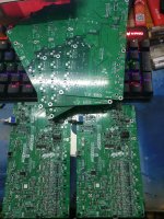
TRANSLATION: Mine is almost ready, but to save money, I hand-soldered it myself.我的也快做好了,为了省钱,我自己手工焊接了。
English please

Member
Joined 2018
Hello, ghfgh-San,
Thanks for evaluating FreeDSP OCTAVIA ver1.00
We're expecting your follow‐up report.😊
CyberPit
Thanks for evaluating FreeDSP OCTAVIA ver1.00
We're expecting your follow‐up report.😊
CyberPit
Out of curiousity, I cloned the repo and tried the order process at JLPCB. After I gave it the BOM and CPL files, I got this warning message:

Is this because those are the through hole components that I would solder myself? Or is there a problem with I uploaded the project to JLPCB?
FYI, the quote for quantity 5 seems to be $350 before shipping, so about $75/each? Does that sound right? Then there's also the additional through hole components.
Last edited:
Member
Joined 2018
Hello, sychan-San,
Your listed parts are NOP (Not Populated).
So, you can ignore this error message and continue your order operation.
(The next step will rotate parts...)
Of course, you need some additional TH parts and cards(if you need them).
CyberPit
Your listed parts are NOP (Not Populated).
So, you can ignore this error message and continue your order operation.
(The next step will rotate parts...)
My previous order was $378.83 (w/o shipping cost) At that time, the parts price was raised, which was the cause of the market shortage.FYI, the quote for quantity 5 seems to be $350 before shipping, so about $75/each? Does that sound right?
Of course, you need some additional TH parts and cards(if you need them).
CyberPit
Last edited:
@CyberPit Thanks for the explanation, I looked more closely at the BOM spreadsheet and found the NoPop sheet.
Thank you for your patient explanations, I am almost entirely a software person, so please excuse the low level questions (it is only just recently that I got good enough with a soldering iron to assemble a crossover without a big mess).
By cards you mean the Amanero USB->I2S, Raspberry Pi or USBi cards, right?
Thank you for your patient explanations, I am almost entirely a software person, so please excuse the low level questions (it is only just recently that I got good enough with a soldering iron to assemble a crossover without a big mess).
Of course, you need some additional TH parts and cards(if you need them).
By cards you mean the Amanero USB->I2S, Raspberry Pi or USBi cards, right?
- Home
- Source & Line
- Digital Line Level
- FreeDSP OCTAVIA