Member
Joined 2018
The PCBA board has arrived!

It will be built this weekend...
CyberPit
It will be built this weekend...
CyberPit
Member
Joined 2018
Now the evaluation has begun!


Functionality check is going. Measurement will be later today...
CyberPit
Functionality check is going. Measurement will be later today...
CyberPit
A tip if someone need more FIR taps on low to mid freq channels of ADAU14xx. A channel can be routed back to the hardware resamplers. So downsampling will reduce the number of FIR taps needed for same frequency resolution. Then the channel can be routed back again for hardware upsampling if needed.
It can also be a good idea if iir filters are needed in low bass channels and high input sample freq is used eg 192 khz.
Big difference of sample freq and iir filer freq can generate harmonics because of truncation error.
8x2 ch of hardware resamplers are quite a lot. And they are very good quality
It can also be a good idea if iir filters are needed in low bass channels and high input sample freq is used eg 192 khz.
Big difference of sample freq and iir filer freq can generate harmonics because of truncation error.
8x2 ch of hardware resamplers are quite a lot. And they are very good quality
Member
Joined 2018
FreeDSP OVTAVIA(Version 0.33j ) Measurement Result Part-1
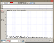
PCM1808 is used for Analog Source Input.ADC to SPDIF OUTPUT Distortion Performance Test (-1dB FS)

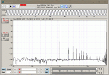
ADC to SPDIF OUTPUT DIstortion Performance Test (-3dB FS)
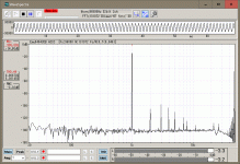
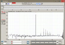
ADC to SPDIF OUTPUT Best Distortion Performance was @-13dB FS
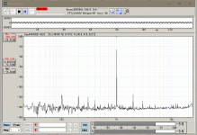
ADC to SPDIF OUTPUT Remain Noise (96kHz BW)
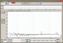
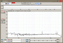
ADC to SPDIF Frequency Response (Sweep, 96kHz BW)
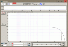
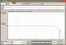
ADC runs at 48kHz, but ASRC upsamples to 96kHz.
Attachments
Member
Joined 2018
FreeDSP OVTAVIA(Version 0.33j ) Measurement Result Part-2
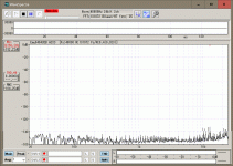
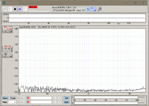
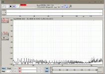
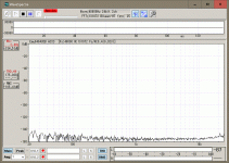
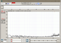
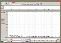
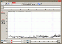
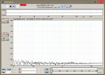
PCM5102A is used for Analog Output and OPA1632 Differential Line Driver is attached to each output. The feeding signal from USB input shows the actual DAC part sound performances.USB to Analog Output Distortion Performance (96k BW)
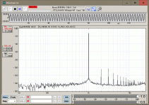
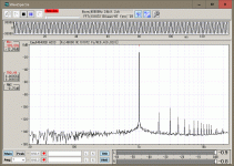

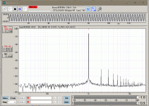
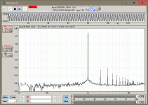
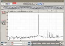
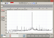
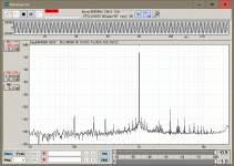
CH7/8 Lower Frequency Noise Spectrum Comes from Surround Mains Power Cable (50Hz/100V) Effect, Please Ignore it. (The following spectrum does not exist..)
Best Disrotion Performance @-10db FS (Ch8)
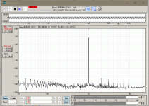
Analog Output Remain Noise Performance (96kBW)
Attachments
Last edited:
Member
Joined 2018
FreeDSP OVTAVIA(Version 0.33j ) Measurement Result Part-3
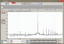
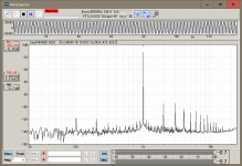
Analog Input to Output Overall Analog-Audio Performance TestAnalog Input to Differential-Analog Output Overall DIstortion Performance (48k BW)
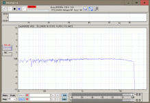
Analog Input to Differential-Analog Output Frequency Response Performance (96k BW)
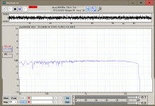
Analog Input to Differential Analog-Output through the DSP Remain Noise (96k BW)
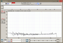

Functional Evaluation Result
There were 2 small workarounds exist. One is the muting logic control part at Combo384 USB-Input. the other is needed to attach 10uF on the DSP-Reset Button contacts. I will start fixing and designing Modification to change the RCA-pin Jack from MJ-519 to RCJ-2223. The GitHub page and my project homepage will be updated soon.CyberPit
Last edited:
Member
Joined 2018
FreeDSP OVTAVIA(Version 0.33j ) Measurement Result Part-4
I would like to add some measurement results...Analog Input to Differential-Analog Output(48k BW)
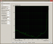
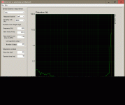
Typical known PCM1808 ADC characteristics.
S/PDIF Optical-Input to DAC Frequency vs. Harmonic Distortion
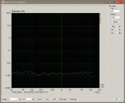
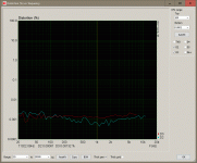
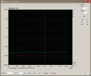
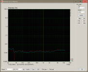
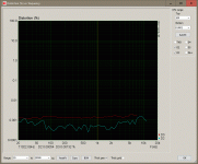
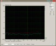
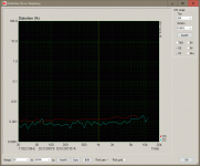
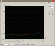
Some of the channels indicate good performance, but the differences between channels are not so much.
CyberPit
Member
Joined 2018
New findings, connecting AGND and DGND at this point, increase the signal-to-noise ratio.

So I added a jumper resistor on the latest version PCB design.

And RCA-pin jacks are changed to RCJ-2232

Additional workarounds in version 0.33J issues are fixed.
Finally, I released FreeDSP OCTAVIA version 1.00

Now FreeDSP OCTAVIA version 1.00 Design is possible to download from the FreeDSP GitHub Page.
I want to say thank you to every person who related to this thread.
Special thanks to Ludwig-San, who sincerely joined this development.
CyberPit
So I added a jumper resistor on the latest version PCB design.
And RCA-pin jacks are changed to RCJ-2232
Additional workarounds in version 0.33J issues are fixed.
Finally, I released FreeDSP OCTAVIA version 1.00
Now FreeDSP OCTAVIA version 1.00 Design is possible to download from the FreeDSP GitHub Page.
I want to say thank you to every person who related to this thread.
Special thanks to Ludwig-San, who sincerely joined this development.
CyberPit
Member
Joined 2018
Hi CyberPit-San,
thanks for your great work bringing out version 1.0 and all the measurements you have done. With your latest finding of connecting AGND and DGND the measurements look really good.
If I have seen it correctly on previous version they were connected just by the ferrite bead FB1. I was wondering if the same result can be achieved by just swapping FB1 with a 0 ohm resistor. Have you tried that as well?
BR Ludwig
Does this mean that its time for the group buy? I'd be interested in getting a board - I have some unused RPi 3Bs sitting around, as well as some amps and drivers!
Regarding the group buy, I can update my mouser and digikey lists to accomodate all the changes. I guess the pricing will not change much to the pricing I presented before (probably a few dollars more to the 4 lay PCB). I can give an up to date price estimate once I updated the lists.
@CyberPit If I remember correctly you ordered 10 boards. Did you buy them all for your local community or do you still have boards left that you want to get rid off?
BR Ludwig
@CyberPit If I remember correctly you ordered 10 boards. Did you buy them all for your local community or do you still have boards left that you want to get rid off?
BR Ludwig
Member
Joined 2018
Thanks for your support and also those who are interested in this design.
Sorry, Sold Out!
CyberPit
Well, I had ordered 10 PCBA boards, and all of them were purchased by local committee members.@CyberPit If I remember correctly you ordered 10 boards. Did you buy them all for your local community or do you still have boards left that you want to get rid off?
Sorry, Sold Out!
CyberPit
No worries, I just wanted to avoid that we order bunch of boards if you have still some laying around with no use.
Member
Joined 2018
If I have seen it correctly on previous version they were connected just by the ferrite bead FB1. I was wondering if the same result can be achieved by just swapping FB1 with a 0 ohm resistor. Have you tried that as well?
You can try to connect the J1-pin1 and J27-pin1.
The attached spectrums are tested on the ver0.1 board.
Bead Only
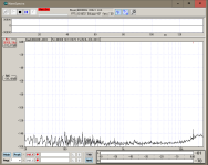
J1-pin1 and J27-pin1 connected with Wire
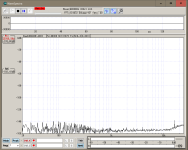
CyberPit
CyberPit, do you have Analog Input to Analog Output Overall Distortion Performance 96k, instead of 48k?
I'm need to replace my aging PCI sound card which I use for a second purpose as measurement interface, so your creation is quite logical replacement.
I'm need to replace my aging PCI sound card which I use for a second purpose as measurement interface, so your creation is quite logical replacement.
Member
Joined 2018
Hi LinuksGuru-San,
The FreeDSP OCTAVIA PCM1808 ADC runs at 48kHz, because it's a Deta-Sigma ADC behavior performance reason. But the DAC runs at 96kHz.
Before starting the measurement of ADC-DAC through performance, I checked the equipment's performance.
The signal source is Toppoing D10(96kHz). FFT Analyzer ADC is modified E-mu 0404USB(96kHz).
Measurement System
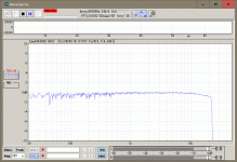
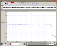
FREQUENCY RESPONSE
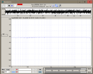
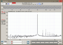
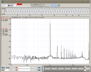
DISTORTION (0dB FS)
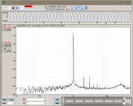
REMAIN NOISE
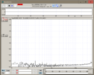
FreeDSP OCTAVIA ADC through DAC Overall
FREQUENCY RESPONSE
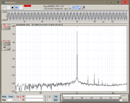
DISTORTION (-0.8dB FS, -3.8dB FS, -12dB FS)
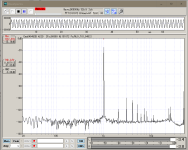
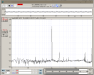
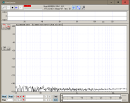
REMAIN NOISE
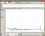
CyberPit
The FreeDSP OCTAVIA PCM1808 ADC runs at 48kHz, because it's a Deta-Sigma ADC behavior performance reason. But the DAC runs at 96kHz.
Before starting the measurement of ADC-DAC through performance, I checked the equipment's performance.
The signal source is Toppoing D10(96kHz). FFT Analyzer ADC is modified E-mu 0404USB(96kHz).
Measurement System
FREQUENCY RESPONSE

DISTORTION (0dB FS)

REMAIN NOISE

FreeDSP OCTAVIA ADC through DAC Overall
FREQUENCY RESPONSE

DISTORTION (-0.8dB FS, -3.8dB FS, -12dB FS)


REMAIN NOISE

CyberPit
Last edited:
Well also the same thing in Japan, In Akihabara many parts shops are getting closed and turning to Anime/Figure shops. Only a few shops keep various stocking electric components.
BTW, I evaluated LM317G circuit and I found a mistake in the upside-down value of the resistor divider. 😵
The attached circuit is a fixed PSU for version 0.33.
[...]
You may consider a reverse diode across the LM317s for protection, as in figure 9 of the TI datasheet, and bypass caps across R58/R59 could also clean up the 3.3V/5V rails.
Last edited:
- Home
- Source & Line
- Digital Line Level
- FreeDSP OCTAVIA
