My freedsp fired up from the first time and works like a dream! Big thanks and kudos to the designers for providing such a great project to the community 😉
I designed my first open baffle speaker in couple of hours thanks to this project 😉
I designed my first open baffle speaker in couple of hours thanks to this project 😉
hello,
I'm interested FreeDSP board, components, or entire finished module.
What and at what prices you can offer, or where it can be ordered.
Thank you.
Jiri
I'm interested FreeDSP board, components, or entire finished module.
What and at what prices you can offer, or where it can be ordered.
Thank you.
Jiri
Hello Jiri,
there is currently no group buy for the freeDSP CLASSIC. However, you can download all necessary files to build one yourself on the website. If someone prepares new kits, we will spread the news in the newsletter, which you can find as well on the website.
Best,
Sebastian
there is currently no group buy for the freeDSP CLASSIC. However, you can download all necessary files to build one yourself on the website. If someone prepares new kits, we will spread the news in the newsletter, which you can find as well on the website.
Best,
Sebastian
Hi there,
I had freeDSP soldered recently, and for the last couple of days I've been struggling to make it work. The firmware is passed to EEPROM via Arduino Nano, but it seems that ADAU1701 doesn't read it on startup and I don't get any signal on output.
Things I've checked:
1. All pins that should be driven to ground or 3.3V are fine.
2. Current consumption of powered ADAU1701 is 106 mA (quartz enabled) or 60 mA (quartz disabled). The numbers fall in normal range from datasheet.
3. Firmware can be written to EEPROM and can be read by Nano.
However, not everything was fine:
1. ADAU17071 pins 13 (1.8V digital supply) and 14 (GPIO) were short-circuited for some time.
2. I didn't find 2N7000 transistor and 24AA256 EEPROM at my local store, so I bought BSS295 and 24LC256. Later I found out that EEPROM is written with 4V instead of 1.8V, and 4V is the maximum voltage ADAU1701 can tolerate (as per datasheet).
With this points in mind, I'd like to ask following questions:
1. Is it likely that my ADAU1701 is dead? How can I check it?
2. Can anybody provide a simple SigmaStudio project or hex file that is known to work on freeDSP (something extremely simple, like [white noise] -> [DAC] or [ADC] -> [DAC]).
3. Can I verify that firmware is actually written to EEPROM and then read by ADAU?
Any other feedback would be appreciated. I have got a multimeter and Hantek 6022be oscilloscope for debugging.
Thanks!
i'm working on a low cost built and tested 1701 DSP card, that has 2V rms output capability. more details in a few weeks
Anyone knows how to increase output level on FreeDSP? Seems a bit low.
I used a pair of dual op amps with AV=4, pot on the input, outboard +-5V supply.
I was thinking of simply changing the resistor values at the output buffer, I need to utilise existing classic dsp. I have an option to change gain for gainclone that is behind it too.
Whatever I do, I unable to download schematics in readable format. It says it's in vector format, but when I zoom in only pixels enlarge. Looks like a bitmap to me.
Does anyone have this in real vector format?
Does anyone have this in real vector format?
Hi,
I have issue with my freedsp board, and Ludwig looks very busy to provide me support.
I made a simple code - attached bin and hex files renamed as txt for diyaudio forum
I uploaded it to the EPROM - ok with a non standard method:
I used a raspberrypi.
But I check the eprom code by switch off and on the power of the raspberry pi, restarted it, and the eprom code downloaded is the same as the eprom code uploaded.
The DSP is powered by the +5v of the raspberry pi. Led is green.
Sound is plugged on ADC0 and 1 - I checked the input source with my amplifier - OK
Nothing is outputed from my freedsp on VOUT-0 to 3
can someone can check my files? Or help me to debug my errors? Or send me a simple valid bin file?
many thanks
Attachments
As for me, I've never managed to upload firmware to ADAU1701 just by writing binaries to the EEPROM (24LC256 in my case). Neither using proposed Arduino Nano approach, nor using other MCUs. The thing that worked out was to pick SigmaStudio HEX file, convert it to Intel hex format using "Sigma Studio Hex File Converter" tool and then upload the resulting file via a clone of Pickit 2 programmer.
Many things can be a potential cause. Bad Nano (in my case), wrong padding bytes (maybe 0xff instead of 0x00 to fill the rest of EEPROM?), wrong program placement. Unfortunately I've never investigated why this had happened to me and what to do if don't have an EEPROM programmer.
Many things can be a potential cause. Bad Nano (in my case), wrong padding bytes (maybe 0xff instead of 0x00 to fill the rest of EEPROM?), wrong program placement. Unfortunately I've never investigated why this had happened to me and what to do if don't have an EEPROM programmer.
As for me, I've never managed to upload firmware to ADAU1701 just by writing binaries to the EEPROM (24LC256 in my case). Neither using proposed Arduino Nano approach, nor using other MCUs. The thing that worked out was to pick SigmaStudio HEX file, convert it to Intel hex format using "Sigma Studio Hex File Converter" tool and then upload the resulting file via a clone of Pickit 2 programmer.
Many things can be a potential cause. Bad Nano (in my case), wrong padding bytes (maybe 0xff instead of 0x00 to fill the rest of EEPROM?), wrong program placement. Unfortunately I've never investigated why this had happened to me and what to do if don't have an EEPROM programmer.
Please, can you post a simple hex file working fine with the ADC in and out ?
It may help me to understand if I have a hardware issue
I don't have FreeDSP any more, but the attached file was definitely working. It is an attempt of creating a guitar overdrive effect, probably with unreasonably high gain, so please don't expect clean sound.
And I'd say it's unlikely that you do something wrong when creating a hex file.
And I'd say it's unlikely that you do something wrong when creating a hex file.
Attachments
I have joined the freedsp community with my nanodsp board. the main difference with the classic is that it has no expansion connectors, but has 2Vrms out, with pop suppression/mute. choice of input connectors cinch or xlr balanced for mono active speaker operation. out choices are cinch, XLR or screwterminals. now built and tested available at https://www.htfelectronics.nl/en/nano-dsp.html
can this pcb works with other dacs?
i need 1 rca input spdif and tuned 4 rca output spdif with 44.1 support in both sides. Is this real?
i need 1 rca input spdif and tuned 4 rca output spdif with 44.1 support in both sides. Is this real?
Last edited:
I solved my issues. It was an hardware issue.
So I am able now to upload and download eprom from RPI
So I am able now to upload and download eprom from RPI
Sent you PM.
Thanks,
Ed Perkins
Thanks,
Ed Perkins
FYI,
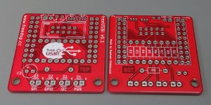
I have a couple of freeUSBi bare PCBs available if anyone needs as I ordered a bunch of them from Elecrow. Usual Elecrow quality, red solder mask. 2 euro per piece plus postage, 2 euros Europe, 2.50 euros elsewhere.
- Home
- Source & Line
- Digital Line Level
- freeDSP - an open source 2-in 4-out digital crossover board