The rear chamber is 15 inches wide on the plan sheet because I plan on making the box 1 inch thick (including the driver access end of the chamber) on all four sides. I failed to mention that on the sheet and didn't show any wood work or bracing plans there at all.
This shouldn't be necessary if you brace the chamber. It's just a whole lot of work to double up all those panels.
Doubling up the panels ANYWHERE is going to be a huge pain with OSB. The stuff is not flat, you can't use glue, and it's going to take a few tubes of construction adhesive to fill in the voids because it's so far from flat.
Yep, its all wasted space. Its a poor practice to fold and leave that much wasted space, but I don't mind. Its a big cab and I'm not concerned about a few extra cubic feet. Wood is cheap and it needs to be braced heavily, so there is an opportunity to add a bunch.
I would very strongly reconsider having any wasted space. You could use that space to make the box smaller OR make the horn bigger. Wasted space is just ... a waste.
You CAN do it without wasting space, even your irregular flare shape can be folded without waste. But it would require a lot of 180 degree bends instead of your two 90 degree bends.
I measured it correctly through the center of the horn path, from the center of the throat to the center of the mouth, using advanced centerline through the corners. Your Orange centerline on your image....
Good stuff.
You are 100% correct on all points made. I cannot measure my driver as I don't know how to do that. If it requires tools other than what I already have, then it'll never get measured cause I won't spend the money for tools I may not use often.
You can make a jig to measure impedance for about 2 dollars in parts. You probably already have the parts anyway so it wouldn't cost anything. You just need a resistor in the 100 ohm range (exact value doesn't matter as long as you know what it is) and a couple of 3.5 mm jacks. Plans for the jig are all over the internet, simple ones and much more complicated ones. I use the dead simple one. Use the jig with free LIMP (ARTA) program or REW to measure impedance and derive t/s specs. It doesn't cost anything.
I remember the large coil issue. I stayed up all night reading about that, searching threads and posts and probably found the majority that has been written about that. Some of your posts narrowed it down pretty well, as to which drivers are most likely to be affected. Its no sure bet, but after reading all you and others discussed, I doubt if my driver is one of those lepers. I could be wrong. Don't think so though.
I wouldn't say those type of drivers are lepers - that's just the cost of ultra high excursion drivers. And I will almost guarantee your driver is one of them. I can link you to my paper if you want.
If you are able to measure frequency response with a mic and you are willing to put the driver in a small sealed box and measure it I will prove it does need the adjustment. Of course it would also be best if you could measure the t/s parameters, as that is a big part of proving the issue.
Now.... since I need to re sim and re fold anyway...
This being an outdoor sub, and flat response being less than optimal in many cases as you have noted... in your opinion, what sort of response should I be aiming for? Got an example handy that I can look at?
I would very seriously recommend that you have another look at the early examples, your first sim that you posted, the small 500 liter sim I posted and the 1500 liter sim GM posted.
It looks like your current sim is standing right around 660 liters and you've got maybe 300 liters of wasted space in there. So call it 1000 liters. I think you can do a lot better with 1000 liters.
If you want the higher tuning I can do another sim, but the sims I do will usually have the more traditional horn shaped flare. If you absolutely don't want the rising response I can sim up something like that too, but my sims are not going to be ruler flat like yours, they will have some bumps because that's actually a good thing.
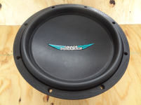
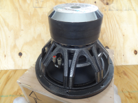
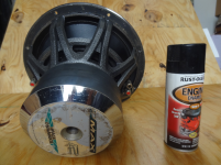
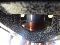
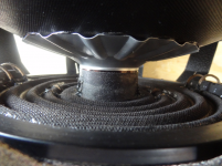
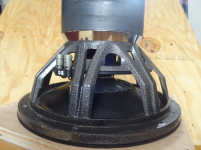
Some driver pics I just took. Not relevant to this build but I can, so I am. 😀


Old skool... Thats my storage box in a couple of those pics with cutout for the driver in the top, the lid isn't shown. Thats a 2 inch VC, nowadays they are bigger. Magnet stack is 3" high x 6.5" diameter. Cast aluminum basket. Thin, high roll rubber surround. Woven fiber (unknown material, I forgot) one-piece cone, less than 150 grams and stiff as a brick. Weight is over 24 lbs on my cheap bathroom scale.
Old skool... Thats my storage box in a couple of those pics with cutout for the driver in the top, the lid isn't shown. Thats a 2 inch VC, nowadays they are bigger. Magnet stack is 3" high x 6.5" diameter. Cast aluminum basket. Thin, high roll rubber surround. Woven fiber (unknown material, I forgot) one-piece cone, less than 150 grams and stiff as a brick. Weight is over 24 lbs on my cheap bathroom scale.
Attachments

This shouldn't be necessary if you brace the chamber. It's just a whole lot of work to double up all those panels.
Doubling up the panels ANYWHERE is going to be a huge pain with OSB. The stuff is not flat, you can't use glue, and it's going to take a few tubes of construction adhesive to fill in the voids because it's so far from flat.
I was taking the shortcut... but you are right about OSB so I'll brace the box instead.
Maybe I should just use 3/4" OSB since the cabinet is gonna need to be quite stiff. I'll do that if I can find some industrial strength wheels to put under it!
You CAN do it without wasting space, even your irregular flare shape can be folded without waste. But it would require a lot of 180 degree bends instead of your two 90 degree bends.
I'll do that too. I agree its dumb to waste. Its a (feeble) excuse to make it bigger too, since I'm liking big. There is still the rear chamber box to deal with after a tight fold though... gotta put that somewhere and its likely to be an ugly fit. I imagine the driver may have to be mounted upside down. If the DUMAX BL curve is representative of my driver then it should work OK like that.
Good stuff.
I'm impressed with the advanced centerline method! THANKS to soho54 and yourself for turning me on to it!
You can make a jig to measure impedance for about 2 dollars in parts. You probably already have the parts anyway so it wouldn't cost anything. You just need a resistor in the 100 ohm range (exact value doesn't matter as long as you know what it is) and a couple of 3.5 mm jacks. Plans for the jig are all over the internet, simple ones and much more complicated ones. I use the dead simple one. Use the jig with free LIMP (ARTA) program or REW to measure impedance and derive t/s specs. It doesn't cost anything.
I had no idea it could be that easy! Yes, I have the resistors and jacks. I'll research and put a jig together. I'm sure there are tutorials somewhere that explain the measuring process too. Thanks again, the great tips just keep on coming my way!
I wouldn't say those type of drivers are lepers - that's just the cost of ultra high excursion drivers. And I will almost guarantee your driver is one of them. I can link you to my paper if you want.
If you are able to measure frequency response with a mic and you are willing to put the driver in a small sealed box and measure it I will prove it does need the adjustment. Of course it would also be best if you could measure the t/s parameters, as that is a big part of proving the issue.
If your paper on the large VC issue is linked in this thread already I'll find it. If not, then yeah I'd love to read it if you have the link handy.
By putting the driver in a small sealed box to measure... can I seal up my storage box and use that? Its very small, just large enough to hold the driver vertical for storage. Maybe 3/8 inch clearance from the backplate of the driver to the bottom of the box max. I can make another box if I need to. Think it will work or should I make sawdust?
I don't have a microphone, can I buy any cheap ones or does it need to meet certain quality/capability specs?
I would very seriously recommend that you have another look at the early examples, your first sim that you posted, the small 500 liter sim I posted and the 1500 liter sim GM posted.
It looks like your current sim is standing right around 660 liters and you've got maybe 300 liters of wasted space in there. So call it 1000 liters. I think you can do a lot better with 1000 liters.
Ok, understood. I think I can make a rising response, no problem. I think I can do better using my cabinet space too. I'll start over with measured T/S.
Thanks,
This is the impedance jig I use (this is actually a friend's, mine is similar, uses the same wiring but I just taped mine up instead of having a plastic case).
https://sites.google.com/site/amateuraudio/projects-1/arta-limp-and-or-room-eq-wizard-impedance-jig
This page has a link to my large coil simulation accuracy and adjustment paper.
https://sites.google.com/site/amate...coil-simulation-accuracy-issue-and-adjustment
Most mic capsules should be fairly accurate in the range a sealed box is going to play. I got lucky with a laptop once and was able to use the laptop (with the built in mic) to measure stuff. I had to do a lot of comparisons with known good measurements to verify it was accurate. I've never had another laptop since that measured accurately though.
There are very inexpensive panasonic mic capsules that are known to be very flat in the reasonable audible range, maybe $2, but shipping will usually cost a lot more than the capsule. Most newer moderate to high end HT receivers come with a mic for setup, these should work fine. The problem is that no matter what you do you have to verify the equipment and measurement procedure are giving accurate results. So you need a known good measurement to calibrate your equipment and procedure. Or you can pay for a known good mic and just use it. For $100 you can get a really nice calibrated usb mic.
Instructions for LIMP and ARTA and REW software are included with the program download. Those two programs will both measure frequency response and t/s parameters, both are free also. There are others (speaker workshop, holm impulse, etc) but I like LIMP for t/s and REW for frequency response.
Some laptops don't have a line in jack. This guy in the following link bought a cheap ebay usb soundcard for $10, took the soundcard out of it's case and put that and the jig all in one housing for a self contained LIMP jig, very similar to a WT2 or WT3 (but bigger).
I have this same $10 usb sound card that I use with my LIMP jig but I didn't bother putting it all in a self contained unit. If I was going to do that I'd put it all in the sound card case, the jig itself is small enough that it could all fit right inside the little blue soundcard case with just the wires coming out.
This is a tiny little sound card, it fits in the palm of your hand and it does what it's supposed to do and plays nice with LIMP. I've had soundcards in the past that LIMP didn't like so much.
Self-contained LIMP jig. - Techtalk Speaker Building, Audio, Video Discussion Forum
The soundcard itself is detailed in post 11 of the link above. You CAN get it for $10, although some ebayers are asking $100+ for it, so look out.
I use the soundcard all the time, also as an actual soundcard as my laptop has TERRIBLE line out sound. It's the only laptop I've ever seen that had bad sound - there's no bass at all. I got it on a refurb deal but it was originally a VERY expensive Asus and even my crappy little 5 year old netbook has better line out sound than this mid/high end Asus laptop.
Last edited:
I have only read upto and including post22.
Take a long look at Danley's Labhorn paper.
He got very good 35Hz performance from a 600litre horn using a pair of designed for purpose drivers which needed to be stacked for any Pi space loading, or bigger.
i.e. for Pi space he used 1200litres, 2Pi space needs 2400litres and 4Pi space needs 4800litres.
His response can extend down to ~28Hz when properly loaded. Some extension wings to double the mouth area and one box using 2 boundaries can get there.
A non truncated horn, i.e. mouth circulference ~ low frequency wavelength AND length =½wavelength from the old fashioned empirical methods gives you the starting data for a horn.
Truncating down to half mouth (& ~half length) area gives ripples.
Portable down to 20Hz is a non starter.
I have only read upto and including post22.
Take a long look at Danley's Labhorn paper.
He got very good 35Hz performance from a 600litre horn using a pair of designed for purpose drivers which needed to be stacked for any Pi space loading, or bigger.
i.e. for Pi space he used 1200litres, 2Pi space needs 2400litres and 4Pi space needs 4800litres.
His response can extend down to ~28Hz when properly loaded. Some extension wings to double the mouth area and one box using 2 boundaries can get there.
You are right about the 35 hz performance, here's the measurement that used to on the prosoundweb Labhorn page.

But you will never get anywhere near 28 hz no matter how many of them you stack. You would be lucky to get 32 hz with 8 units properly stacked. And that big dip right about the low knee will never go away.
The Labhorn was originally designed to be a near full size horn with a 26.4 hz flare. But in the folding process it changed a lot, the flare was radically changed and made smaller and the rear chambers were dramatically undersized causing the big dip above the low knee. The folded Labhorn is not a very good horn.
A non truncated horn, i.e. mouth circulference ~ low frequency wavelength AND length =½wavelength from the old fashioned empirical methods gives you the starting data for a horn.
Truncating down to half mouth (& ~half length) area gives ripples.
Portable down to 20Hz is a non starter.
Portable down to 20 hz is absolutely possible, and you can do it without any ripples too if you want. I believe I already posted a measurement of a 35 hz flh I made with almost ruler flat response in a cab size under 100 liters.
If you use traditional horn math and make a truncated horn you will indeed get a rising response with some ripple, that's not necessarily a bad thing.
An externally hosted image should be here but it was not working when we last tested it.
That's a Labhorn sim, and it correlates pretty well with the measurement in the last post. The light grey line is a single unit, the dark black line is 8 units stacked properly (to make the combined mouth as square as possible).
As you can see you will never get below 32 hz with a stack and the dip above the low knee will never go away. And if you stack them improperly (like in a line as opposed to a stack as many people do) you won't even get the performance shown in this sim.
Even with 32 units stacked the low knee is only 30 hz (not 28 hz) with a 28 hz f3, although to be fair with 32 units the dip above the low knee does go away. But 32 units is an impractically large stack.
I don't think your 100litres can be referring to a horn volume for 35Hz lower limit.................Portable down to 20 hz is absolutely possible, and you can do it without any ripples too if you want. I believe I already posted a measurement of a 35 hz flh I made with almost ruler flat response in a cab size under 100 liters................
Are you talking about tapped horn, or vented, or sealed, or quarter?
Thanks for the links and info just a guy. Your paper shows a lot of work and effort put into it, I'll study that thoroughly.
I'll get that USB sound card on the way. I have no idea what to do about the mic though, unless I can pry loose $100 for a UMIK. I found a DIY mic plan on the 'net using a panasonic module a few weeks back and I can build that one, but calibration is the issue. I have nothing to compare to for verification so the UMIK looks like my only option a this point. But as you know by now I tend to make too many assumptions about things I have no knowledge/experience with so I'll explore the mic issue a bit... and if no other trusting option can be found I'll get the UMIK.
Isn't it great when universe (through others in my case) prompts ya' to start all over again from scratch? Opportunity for more fun sometimes seem endless.
@ AndrewT,
I can't speak for just a guy but if I recall correctly the 100 liter 35 Hz FLH was shown early in this thread. I've read this thread a few times now.... think its back there somewhere. If not I apologize for wasting time.
I can't speak for just a guy but if I recall correctly the 100 liter 35 Hz FLH was shown early in this thread. I've read this thread a few times now.... think its back there somewhere. If not I apologize for wasting time.
I don't think your 100litres can be referring to a horn volume for 35Hz lower limit.
Are you talking about tapped horn, or vented, or sealed, or quarter?
It's a flh with a weird flare shape designed specifically for flat response with very little ripple. I did it just to see if I could.
Here's the measured response (it was winter so this is in room with mic right at the horn mouth). The top trace is the ~ 100 liter flh, the bottom trace is a ~ 60 liter tapped horn.
An externally hosted image should be here but it was not working when we last tested it.
[/QUOTE]
This is an early iteration of the sim, not the final version. I don't think I have a final version of inputs as I was still making changes as I was building it. The final version was a bit bigger and with a bit higher tuning than this sim shows.
An externally hosted image should be here but it was not working when we last tested it.
This is a build pic. The driver is a 6 inch tang band w6-1139 so you can see this isn't a big horn. You can also see the flare shape is very odd. The mouth hole was not cut out yet at this point but it was later cut out in the area that I drew in green. The access panel hole is shown in this pic without the access hole cover in place.
An externally hosted image should be here but it was not working when we last tested it.
So yeah, flat (not rising) response down to 35 hz. The dip at 90 hz was a bit deeper than expected (and I never really investigated why) but it's not that bad.
You can get whatever response curve shape you want if you play with the horn geometry. This was just an experiment to see if I could get flat (not rising) response with no ripple down to 35 hz from a very small flh and it was pretty easy. I could have gone about 30 liters smaller and had approximately the same response too. The panels were precut and I decided to just leave them larger than necessary, so the whole part from the last bend to the mouth was 2 or 3 inches wider than I originally planned. It didn't hurt anything but it didn't really help anything either, I could cut 3 inches off the back of the horn (making it maybe 20 liters smaller) and it would still function pretty much the same.
It's even easier to go lower with a tapped horn in an even smaller size, as you can see by the measurement (lower trace of the ~ 60 hz tapped horn).
Just for fun here's another measurement of the same small ~ 60 liter tapped horn, but this one was taken outside at a distance of about 10 meters and with a handful of stuffing in the mouth. I don't think I have any build pics of that horn but here's a little write up on it. https://sites.google.com/site/amateuraudio/projects-1/tapped-horn
This was built back in 2008 shortly after Hornresp upgraded with ability to sim tapped horns so this was one of the first diy tapped horns. While I was designing it I could only find measurements of 3 or 4 diy tapped horns at the time, and a couple of Danley's measurements - the commercial measurements didn't help much though, as the layout was unknown except for the TH_SPUD, which I modeled this little guy after. And at the time it was hotly debated that tapped horns couldn't be simulated properly so this project was more about learning than anything else.
An externally hosted image should be here but it was not working when we last tested it.
Last edited:
Thanks for the links and info just a guy. Your paper shows a lot of work and effort put into it, I'll study that thoroughly.
I'll get that USB sound card on the way. I have no idea what to do about the mic though, unless I can pry loose $100 for a UMIK. I found a DIY mic plan on the 'net using a panasonic module a few weeks back and I can build that one, but calibration is the issue. I have nothing to compare to for verification so the UMIK looks like my only option a this point. But as you know by now I tend to make too many assumptions about things I have no knowledge/experience with so I'll explore the mic issue a bit... and if no other trusting option can be found I'll get the UMIK.
Isn't it great when universe (through others in my case) prompts ya' to start all over again from scratch? Opportunity for more fun sometimes seem endless.
If you have a computer with a sound card with a line in jack you don't need the $10 sound card. (Some sound cards don't play nice with LIMP though, so you might need it anyway.) It's easy to find a working desktop computer with a line in jack, so I wouldn't buy the sound card if you don't need it.
I like the calibrated USB UMIK from cross spectrum labs. This is what I was going to order but then suddenly our economy took a dump and with shipping and exchange rates it would cost almost $200 local currency so I don't need it that bad right at this moment.
Cross·Spectrum - Calibrated MiniDSP UMIK-1 Microphones for Sale
By the way, you CAN use the mic capsule without building the preamp. Just wire the capsule right to a 3.5 mm jack, plug into the mic in jack and measure away. This will give low sensitivity measurements but it works and it's cheap. A $2 capsule, a 3.5 mm jack, and that's the extent of the cost. It shouldn't need calibration in the range you will use it and it should give accurate frequency response with with unknown spl low sensitivity, which isn't really a problem.
Last edited:
Yeah, I just came from the CSL labs site eyeballing the UMIK-1 there. I'm thinking about buying one... gotta sleep on it.
Meanwhile, I'm thinking about a DIY mic for frequency response measurements. The Panasonic WM-61A electret many have used in the past seems to be obsolete now, but I see mentions of possible replacements. This site:
John Conover: Using the Panasonic WM61A as a Measurement Microphone
talks about the Linkwitz mod variations and is loaded with info to make those panasonics a better mic. But if a cheap over the counter mic will work well enough for freq resp measuring I'll just buy one and save my solder.
The UMIK-1 from CSL would be nice to have later on for SPL/response measurement, and since I'm just getting started on building a few speakers, I may talk myself into buying one.
Now then... how to squeeze more currency from a nearly empty wallet... is there an app for that?
EDIT: Forgot to mention I need the cheap sound card so I'm ordering one off fleebay. My laptop (Lenovo T510) has no line in or mic ports, just a headphone port.
Last edited:
Well, I can't argue against your 35Hz results.
Based on that Sp should be able to get to around 20Hz in a portable as you said in post226
It obviously comes down to expertise !
Based on that Sp should be able to get to around 20Hz in a portable as you said in post226
Portable down to 20 hz is absolutely possible,
It obviously comes down to expertise !
It obviously comes down to expertise !
It's just a lot of playing with the simulator. I found early on that a small mouth would counter the rising response of a massively undersized flh (and this is something that specd also found out on his own as his sims demonstrate). And the cigar shape allows for a very flat response with very little (or no) ripple when the horn is ridiculously undersized. But I had to build it to verify that it actually could be done and that it would measure as it simulated.
The 2 db dip at 90 hz was unfortunate and unexpected but it wasn't bad enough to get excited about. It was supposed to be ruler flat out to 120 hz. Oh well.
When comparing these horns against a ported dual driver version with the same drivers (this one with ~ 30 hz tuning - https://sites.google.com/site/amateuraudio/projects-1/small-ported-sub } the single driver tapped horn design had more max spl than the dual driver ported box, quite a bit more, and quite a bit more low end extension too. And the flh was quite a bit louder than the tapped horn. But it was never a very scientific comparison, we just used a plate amp (the Bash 300) with no attempt at using a proper high pass filter, and we used random music tracks (of the bassy variety) to A/B test the subs in a living room. It was all very subjective and not at all scientific.
As far as sound quality, I prefer the tapped horn and I use it without the stuffing in the mouth. It's got a totally different tuning and response curve shape than the flh and the tapped horn is 5/8 mdf while the flh is 3/8 arauco plywood so it's impossible to even guess why I prefer the sound of the tapped horn, but I do.
Last edited:
Also interesting to note is that these drivers (we got 8 of them) were from the first batch (I think) of the SI designation. (They were previously SC and SG I believe in earlier iterations.)
These drivers didn't measure anywhere near published spec. Notably, fs was 10 hz higher than published even after a brutal break in, and even when measured seconds after being forced to massive excursion with high power 10 hz sine waves. This made a tremendous difference in sims.
That's why it's important to measure your t/s specs. Tang band is (or at least was) pretty infamous for playing fast and loose with the specs but you never know what you have until you measure.
I just read your large voice coil paper just a guy. Its a pretty comprehensive collection of data taken from testing you folks did for the problem. Hats off to you all for your efforts. Much appreciated.
I think after reading your paper I'll find that my driver is one of those belonging to the list. In fact, I'll wager it may elbow the UXL classic example into a lower ranking, likely taking top honors. If so, I'll wager it will remain there.
I'll shop for a mic this week and make the impedance jig. Hopefully next week I'll have T/S params and sim a sealed box to build for the Large VC testing. This week can be filled with reading some more in the meantime.
Yeah, well, every couple of years I do a one or two week study on something for fun. This time it was the Large Coil issue, last time (in 2013) it was the centerline vs advanced centerline issue. Horn Folding - a brief study of the centerline vs advanced centerline method - AVS Forum | Home Theater Discussions And Reviews There's some nice quotes from the guy that invented the advanced centerline method in that study.
And sometimes the study is just a non typical project like the ultra flat frequency response flh I showed here (2010? 2011?) and the little tapped horn, there weren't many built and measured tapped horns at that time (2009).
This Large Coil issue was pretty fun to study, it took a couple of weeks of very long days and my dog spilled a cup of coffee on my laptop so the keyboard was not working. I did the entire study, including all the sims, calculations and writing the paper by clicking the mouse using the on screen keyboard located in the MS accessibility menu. THAT was super fun. I didn't even think to use a usb keyboard at the time as I was actively trying to fix the laptop as I was doing the study and I thought I could fix it. It's still broken but I do have a usb keyboard now.
Yes, I will pretty much guarantee your driver is one that is affected by the Large Coil issue. You don't get that much stroke without consequences. It might not be that bad, but without having a published Le spec you can't even estimate how bad it might be.
The worst driver in that study was one of the Fi drivers with normalized inductance (Le/Re) of more than 3. That's ridiculously high inductance and it didn't sim accurately at all. My adjustment method fixed the sims right up though, for all the 22 drivers that were studied. The generic adjustment isn't perfect but it's a lot better than ignoring the issue, and the curve fit method (that you will be doing) gives the best results possible that I am aware of.
Last edited:
Well, hopefully mine won't beat the FI then... Le/Re ratio >3, yikes! Good thing I didn't wager a new UMIK-1 on my prediction huh...
I just went through your site you have some interesting projects there. You been having fun for sure.
I just found this Dayton imm-6 calibrated measurement mic on sale for $12.25 + shipping at Parts Express. The PDF datasheet shows that sensitivity is slightly less than the old Panasonic module and S/N ratio is A weighted (70 Db), so not quite as good as the Panasonic there either, but I'm thinking it should be good enough to get the data I need for T/S and my LVC issue. Ya think?
Edit: The Dayton mic is calibrated to be flat 18 Hz - 20 kHz. Seems pretty decent for a low buck, no soldering, mic. Along with the $11 USB soundcard maybe those two trinkets will be all I need? I'm fishing for someone to talk me down from the UMIK-1 purchase. $100 buys a lot of OSB and glue!
Last edited:
- Status
- Not open for further replies.
- Home
- Loudspeakers
- Subwoofers
- FLH design basics for a dummy