Thats odd the images didn't stick. Here is the first image again:

Second image:

Third image:

Thanks for those tips and info just a guy! I see now that my flare is a difficult one. Question... can I use a non-stretch string to check my path lengths after folding? Or is it irrelevant... since the corners will screw that idea up?
Still studying and not doing much on my folding, as my spare time seems to have vanished. Hopefully soon...
Second image:
Third image:
Thanks for those tips and info just a guy! I see now that my flare is a difficult one. Question... can I use a non-stretch string to check my path lengths after folding? Or is it irrelevant... since the corners will screw that idea up?
Still studying and not doing much on my folding, as my spare time seems to have vanished. Hopefully soon...
Attachments
You should be checking your path lengths as you are folding, not after folding.
Folding is pretty simple but takes awhile if you want it very accurate. If you use the tips I gave you can fold a cab up in a few minutes, although you may have to change your sim to achieve it.
It appears you are trying to invent a new way to fold, that's not required. Folding the old fashioned way is simple enough. Centerline and advanced centerline folding methods are pretty simple and straightforward.
The corners don't screw anything up, the centerline distance around a bend is simply that, the distance through the center line. Advanced centerline distance around a bend is a bit shorter.
In this image centerline folding method is on the far left, advanced centerline is in the middle. (Image credit to soho54.)

As you can see this is a bit different than what you are doing. Extend those triangle lines all the way to the outside edge of the bend, then draw a line through the center line (or advanced center line) and that's your length around the bend.
Folding is pretty simple but takes awhile if you want it very accurate. If you use the tips I gave you can fold a cab up in a few minutes, although you may have to change your sim to achieve it.
It appears you are trying to invent a new way to fold, that's not required. Folding the old fashioned way is simple enough. Centerline and advanced centerline folding methods are pretty simple and straightforward.
The corners don't screw anything up, the centerline distance around a bend is simply that, the distance through the center line. Advanced centerline distance around a bend is a bit shorter.
In this image centerline folding method is on the far left, advanced centerline is in the middle. (Image credit to soho54.)
As you can see this is a bit different than what you are doing. Extend those triangle lines all the way to the outside edge of the bend, then draw a line through the center line (or advanced center line) and that's your length around the bend.
Thanks again just a guy.
I understand all that you explained and I think I can get it done. The main issue I'm having in the corners is the fact that this is my first attempt at folding anything and I don't trust my work!!! Until I can verify I've done something correctly there will be no confidence!
You've been very generous sharing your knowledge and time. None of your efforts will be wasted by the end of this project. Cause I'm hard nosed and won't quit until I hear a fat lady singing the blues!
Until I can verify I've done something correctly there will be no confidence!
Start simple then. Take a single PAR segment and fold it in half.
It's easy to do. First do it the easy way. Add S1 and S2 togther, that's your total box cross sectional area (not counting wood panels). Take L12 and divide it by 2, that's your box length (again, not counting wood panels). Then all you have left to do is draw in the divider panel. Easy as pie.
Then do it the hard way. S1 + S2 is still your total box cross sectional area but if you want the length as accurate as possible you need to plot it out while using the Horn Data info and measuring length around the bend as you go. This can take awhile, even for a single folded segment.
Sometimes it's easier to just draw it out the easy way, then reverse engineer the segment length of what you drew and just adjust the sim to reflect what you drew. It can be a lot easier going that way.
In fact IIRC Ricci designed the Gjallerhorn and Othorn not by folding up a simulation, but by simulating various different folds. So he drew first and then simulated what he drew, taking a LONG time to make changes to the drawing and adjust the sim until he squeezed out every last bit he could get from his chosen dimensions.
There's different ways to go about this, and there's the Sketchup method, which I think you already mentioned and rejected, and I don't think it's a very accurate way to fold anyway.
This can be incredibly easy and fast or incredibly slow (but still pretty easy) depending on how accurate (true to the sim) you want to get and how flexible you are with making adjustments to the sim.
Last edited:
YES!! To all of that just a guy!
I did it just like you said, kinda.. not exactly, but mostly integrating your advice into my plan! I have the entire horn folded into the shape and overall dimensions I wanted as I was planing the layout, including having the wasted space right where I wanted it to be for all the audio/amps gear thats going to be housed on isolation mounting in there.
I began with the mouth and worked backwards. Knowing that the horn is nearly 14 feet long, I wanted to get the aggressive flare end of the horn down first, so the first (and most difficult) corner fold could be done furthest away from the mouth on my projected cabinet length. Figuring approximate lengths of the remainder of the horn I tentatively placed the small S1/S2/Driver box end of the horn where I wanted it to be just above the mouth. I left 9 inches of extra space available at the smallest S1 end so I would have some S1 location adjustment flexibility while folding the two corners. Then I added the remaining middle section.
Its laid out loosely right now using the simple centerline method. I'll work on the corners a bunch more to get them as accurate as I can from this initial layout. A good thing about this big layout plan using only two 90 degree corners is that I still have 9+ inches of S1 location flexibility near the mouth to work with as I tighten up the folds. My projected cabinet length was 80-84 inches initially and it looks like it'll fall within that range easily from this first layout.
Its all good! THANKS AGAIN!!!
You don't really need to bother using advanced centerline to fold if you don't want to. The difference if you use simple centerline method will end up being a few cm discrepancy between the sim and the folded plans. It won't amount to much difference at all.
Advanced centerline is much more important when you are reverse engineering a folded design so you can sim it as accurately as possible. In that case the few cm path length can make a difference as accuracy in simulation is the primary goal in that case.
Anyway, I have no idea what you are doing from your description, but have fun with it. A bit of personal opinion - I don't like dead space and I don't like electronics housed in subs. If you put electronics in a chamber (even if it's open) it's not ideal for cooling. And the cab vibrations will rattle the snot out of your electronics which may potentially lead to premature failure and/or rattling noises. It's also going to add weight to this massive monster that really doesn't need to be inside there. The amp can stay inside at all times, just feed the speaker wire out to the sub in it's various locations. Just my opinions, take it or leave it.
I agree with you on the advanced centerline method. Close would be close enough for this horn, a couple cm in length makes little difference. I just got started on the folding though and I'm learning and understanding a lot more as I go. I slowed down, thinking a bit more. Its still fun too... and I am seeing options in my layout that I hadn't thought about yet. So this is a learning opportunity as well as a task. I'm planning on folding up once using your advanced centerline method as much for the experience as the accuracy. I've come a long way from knowing nothing... ain't gonna leave anything on my plate at this banquet.
The Trapezoid thing doesn't work at all, I was dead wrong about that. It can be done, but not like I thought and outlined. I don't like math so I'm not going there.
Agree with you again on my idea for housing audio gear in the cab. Isolation mounting would be difficult to engineer and expensive to make, not cost effective and probably not vibration damping effective enough. Hot amps are dumb stuff too. As I was playing with folding schemes today I decided to eliminate as much wasted space as I can. Keeping it simple. A one-trick pony...
The sim has been revised down to a smaller ~660 liters (Including 53 L driver box) while performance is improved. I'm looking forward to the end when its time to finish/decorate the cab, but this part of that process is too interesting to hurry past. I'll share it all when I get there.
Have a great weekend,
I'm planning on folding up once using your advanced centerline method as much for the experience as the accuracy.
Just to be clear, it's not my method. I talk about it sometimes but I have nothing at all to do with inventing it.
As far as I know, soho54 tried a whole bunch of different methods (probably all 5 shown in the previous pic and more) using many sims and comparing to many measurements to find the best, most consistent, most accurate method he could find, and it was advanced centerline.
I noticed his work, as did a few other people. That's about all I did.
If I have seen further, it is by standing on the shoulders of giants. -Isaac Newton
With Respect.
With Respect.
I have had great success using a string laid out on a drawing to quickly estimate total path length. It is within a few percent of the advanced centerline method (which is what I use when down to the final design for simulation in a multi segment comprehensive Akabak sim). Starting with a hand sketch on graph paper and using string (or piece of 24 ga wire) will let you estimate feasibility of a design quickly.
^^ xrk971 ^^ Thanks for stopping by! I read a lot of your cool design threads in the full range forums. I'm thinking about building a couple of your ideas after this sub is done. Got my foam core, hot glue, drivers and stuff all ready to go to mock up a couple of your full range designs that may work outdoors with high SPL! Can't wait to get started but gotta finish this beast first...
I actually am using a non stretch, high dollar fishing line to fold this monster. I have a spool of Berkeley Professional grade braided PE line in 30# test diameter that I picked out of my tackle boxes and its working great. I am working on my 3rd (and final?) fold for this cabinet using the advanced centerline method. The first two layouts were great practice and I learned an awful lot about how to get it done accurately. The advanced centerline method is awesome in my opinion. Its so close through the corners that I doubt I'll have to compensate for length anywhere, cause my 2nd fold came out only 3/8" longer path length than simmed! If this 3rd attempt is anywhere near as close as the 2nd was, I'm taking it to the sawdust and glue step.
Thanks,
Hello,
take a step response and a time window 0,5,10,15 msec, than you see how much time it takes, spec. in a corner.
take a step response and a time window 0,5,10,15 msec, than you see how much time it takes, spec. in a corner.
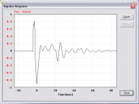
Last time I checked impulse response in a sim was ... hmm let me think ... never.
From the impulse response wiki (since I'm not mathematically inclined to explain things myself) -
https://en.wikipedia.org/wiki/Impulse_response
SO -
1. Everything the impulse response is showing you can be seen in the other graphs Hornresp shows.
2. It's easier to determine what these things mean in the other graphs than in the impulse graph.
3. The impulse response will change as soon as you bandwidth limit things by placing high and low pass filters and eq into the mix.
4. The sim assumes infinitely strong and rigid axisymmetrical construction so the impulse will have at least some margin of error anyway.
5. We KNOW the impulse is going to be a mess because horns use a lot of resonances to product their output - who cares if it's a bit more or less messy.
6. The REAL impulse is probably going to be even worse than simulated because it will contain cone resonances, panel resonances and all kinds of real world garbage.
Even a full size ideal horn doesn't produce a perfect impulse response. It's a lot nicer than these small horns but still not perfect.
Your little horn impulse is a bit of a mess, yeah. Compare it to other things. Here's the impulse of a random file from my records, I just went through a few until I found a funny looking one. It turned out to be a small tapped horn GM posted awhile back. Nice, huh? And you thought yours looked weird. Who cares. It is what it is. Impulse is so incrediby important I don't ever even look at it.
From the impulse response wiki (since I'm not mathematically inclined to explain things myself) -
Since the impulse function contains all frequencies, the impulse response defines the response of a linear time-invariant system for all frequencies.
...
It is usually easier to analyze systems using transfer functions as opposed to impulse responses.
...
Loudspeakers suffer from phase inaccuracy, a defect unlike other measured properties such as frequency response. Phase inaccuracy is caused by (slightly) delayed frequencies/octaves that are mainly the result of passive cross overs (especially higher order filters) but are also caused by resonance, energy storage in the cone, the internal volume, or the enclosure panels vibrating.
https://en.wikipedia.org/wiki/Impulse_response
SO -
1. Everything the impulse response is showing you can be seen in the other graphs Hornresp shows.
2. It's easier to determine what these things mean in the other graphs than in the impulse graph.
3. The impulse response will change as soon as you bandwidth limit things by placing high and low pass filters and eq into the mix.
4. The sim assumes infinitely strong and rigid axisymmetrical construction so the impulse will have at least some margin of error anyway.
5. We KNOW the impulse is going to be a mess because horns use a lot of resonances to product their output - who cares if it's a bit more or less messy.
6. The REAL impulse is probably going to be even worse than simulated because it will contain cone resonances, panel resonances and all kinds of real world garbage.
Even a full size ideal horn doesn't produce a perfect impulse response. It's a lot nicer than these small horns but still not perfect.
Your little horn impulse is a bit of a mess, yeah. Compare it to other things. Here's the impulse of a random file from my records, I just went through a few until I found a funny looking one. It turned out to be a small tapped horn GM posted awhile back. Nice, huh? And you thought yours looked weird. Who cares. It is what it is. Impulse is so incrediby important I don't ever even look at it.
An externally hosted image should be here but it was not working when we last tested it.
Last edited:
Another weird one, a really long really low tuned really small flh. This one saves up all the little wiggles and burps them out in big widely spaced chunks.

Thanks for putting my mind at ease!
I just finished folding my little horn with funny looking IR for the fourth time, full scale on plywood. I learned to fold with confidence and I really like the Advanced Centerline method. That said, I'm ready to share what I got so far.
DISCLAIMER: While I have folded this 4 times using the Adv centerline method, and while I have taken every precaution to accurately document my work, I am human and subject to making human mistakes. If you attempt to use any of the following, please check for possible errors.
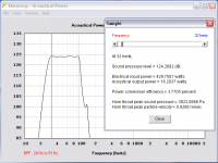
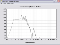
This is a 660 liter FLH (including 53 L rear chamber) tuned to approximately 31.8 Hz knee for a flat response for outdoor use. F3 is ~27 Hz or thereabouts in 2Pi. Raw response varies from 97.2 Db - 97.66 Db @ 1 watt from 30 - 80 Hz, 2Pi, so about .5 Db variance across the band. The following are screenshots taken at 2Pi, as this is an outdoor sub. The Max SPL (~123 Db using 24-91 Hz 8th order BPF) graph is represented by 460 watts and an 18mm excursion limit.


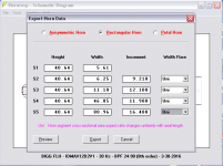
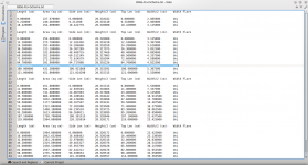
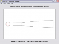
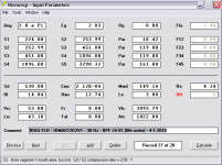
Included below are the Hornresp schematic export text file that shows the fold locations and calculated cross-sectional widths, along with a PDF of the full-scale folded horn after I transferred the dimensions to paper.
EDIT: The PDF drawing is not to scale. Dimensions were simply written on to an approximate drawing of the full scale horn after folding the layout on a sheet of plywood. The measurements should be accurate, the drawing itself is freehand, not to scale.
Edit #2: I talked to Matt Borguart (spelling incorrect?) on the phone about the Le rating for my IDMAX12D2 driver. He did not have his old data files handy at the time, so Le is still a mystery. During our conversation I learned that my IDMAX is a version 1 though, not V2. All parts are the same between those first 2 versions except v1 had three 1 inch thick magnets stacked while v2 and later have two 1.5 inch magnets stacked. It wasn't until v3 that other parts were changed (basket, entire motor core, two-piece cone etc.) and the cone got heavier. I have a stack of three 1 inch thick magnets on my driver so its v1 and relabelled in the sim.
I just finished folding my little horn with funny looking IR for the fourth time, full scale on plywood. I learned to fold with confidence and I really like the Advanced Centerline method. That said, I'm ready to share what I got so far.
DISCLAIMER: While I have folded this 4 times using the Adv centerline method, and while I have taken every precaution to accurately document my work, I am human and subject to making human mistakes. If you attempt to use any of the following, please check for possible errors.
This is a 660 liter FLH (including 53 L rear chamber) tuned to approximately 31.8 Hz knee for a flat response for outdoor use. F3 is ~27 Hz or thereabouts in 2Pi. Raw response varies from 97.2 Db - 97.66 Db @ 1 watt from 30 - 80 Hz, 2Pi, so about .5 Db variance across the band. The following are screenshots taken at 2Pi, as this is an outdoor sub. The Max SPL (~123 Db using 24-91 Hz 8th order BPF) graph is represented by 460 watts and an 18mm excursion limit.
Included below are the Hornresp schematic export text file that shows the fold locations and calculated cross-sectional widths, along with a PDF of the full-scale folded horn after I transferred the dimensions to paper.
EDIT: The PDF drawing is not to scale. Dimensions were simply written on to an approximate drawing of the full scale horn after folding the layout on a sheet of plywood. The measurements should be accurate, the drawing itself is freehand, not to scale.
Edit #2: I talked to Matt Borguart (spelling incorrect?) on the phone about the Le rating for my IDMAX12D2 driver. He did not have his old data files handy at the time, so Le is still a mystery. During our conversation I learned that my IDMAX is a version 1 though, not V2. All parts are the same between those first 2 versions except v1 had three 1 inch thick magnets stacked while v2 and later have two 1.5 inch magnets stacked. It wasn't until v3 that other parts were changed (basket, entire motor core, two-piece cone etc.) and the cone got heavier. I have a stack of three 1 inch thick magnets on my driver so its v1 and relabelled in the sim.
Attachments
Last edited:
A couple of notes - it appears you are simulating with chamber resonances masked. Why?
The external cab width (or depth, depending on how you look at it) appears to be 18 inches, which makes sense because the width at the mouth is 17 inches and you specified 1/2 in wood. So why is the internal width in the sealed rear chamber 15 inches?
Any way 1/2 inch wood? 1/2 inch is ok as long as you use a LOT of bracing, but be aware that actual 1/2 inch is not that common, it's usually 3/8 or marketed as 1/2 but measures 3/8.
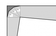
Now on to the picture. What's up with that fold? Is the area I marked in red ALL wasted dead space? If so this is probably the worst case of inefficient use of space I've ever seen and it's fairly inefficient in the use of wood too (blocking in big dead spaces uses wood that you wouldn't need if there was no dead space).
And how did you measure the length? Where did you run the string? Along the line I marked in green or the line I marked in orange? Because of where you put the numbers on the pic and where you put the lines in the corner bends I'm thinking you measured the length of the green line. That would be a mistake. The advanced centerline goes through the center line with the length around the bends advanced slightly towards the inside of the bend.
The external cab width (or depth, depending on how you look at it) appears to be 18 inches, which makes sense because the width at the mouth is 17 inches and you specified 1/2 in wood. So why is the internal width in the sealed rear chamber 15 inches?
Any way 1/2 inch wood? 1/2 inch is ok as long as you use a LOT of bracing, but be aware that actual 1/2 inch is not that common, it's usually 3/8 or marketed as 1/2 but measures 3/8.
Now on to the picture. What's up with that fold? Is the area I marked in red ALL wasted dead space? If so this is probably the worst case of inefficient use of space I've ever seen and it's fairly inefficient in the use of wood too (blocking in big dead spaces uses wood that you wouldn't need if there was no dead space).
And how did you measure the length? Where did you run the string? Along the line I marked in green or the line I marked in orange? Because of where you put the numbers on the pic and where you put the lines in the corner bends I'm thinking you measured the length of the green line. That would be a mistake. The advanced centerline goes through the center line with the length around the bends advanced slightly towards the inside of the bend.
Next up, some notes on the driver itself. I see you spent some time making that frequency response curve ruler flat. I think you are not going to get something that measures anywhere near that.
First, a brand new driver fresh off the line can deviate from published specs by 20 percent and still be considered normal. Unless the manufacturer pays a LOT for quality control the tolerances are pretty loose.
Second, this driver is 16 (?) years old. A LOT of stuff could have happened in 16 years. The surround and spider may have been beat and may be more compliant than the published specs indicate. If the driver was stored with the cone in a horizontal position all this time (instead of vertical) the cone might have sagged and caused a moderate to severe offset from where the coil alignment originally was. The surround and spider might have stiffened up and become LESS compliant than the published specs would indicate.
So there's a few issues that affect new and old driver t/s specs. If you don't measure yourself it's a gamble.
Then there's the large coil issue. Not sure if you are aware, but large coil drivers like this usually don't sim as the t/s parameters indicate. Did we talk about this before? Did you read my paper on the issue and the sim adjustment? I'm betting this driver falls into that category of drivers affected by this issue, and if you click the "large coil" checkbox in the Loudspeaker Wizard you will see your almost perfectly ruler flat response go straight into the toilet. Then add a bit of Re on top of that to simulate a bit of power compression and it just keeps getting worse.
So the chances that the finished product will measure anything like the sim indicates are slim to none. I can't remember if we talked about the large coil issue before but this is why I was suggesting this super flat frequency response is not really a great idea. There are a few reasons it's not ideal.

A couple of notes - it appears you are simulating with chamber resonances masked. Why?
Glad you noticed that. Some time a while back I had switched masking on then forgot to put it back to unmasked. I just corrected that and noticed a slight difference in the response, so I'll probably alter the sim and refold the horn.
The rear chamber is 15 inches wide on the plan sheet because I plan on making the box 1 inch thick (including the driver access end of the chamber) on all four sides. I failed to mention that on the sheet and didn't show any wood work or bracing plans there at all.The external cab width (or depth, depending on how you look at it) appears to be 18 inches, which makes sense because the width at the mouth is 17 inches and you specified 1/2 in wood. So why is the internal width in the sealed rear chamber 15 inches?
Any way 1/2 inch wood? 1/2 inch is ok as long as you use a LOT of bracing, but be aware that actual 1/2 inch is not that common, it's usually 3/8 or marketed as 1/2 but measures 3/8.
For wood I plan on using 1/2" 4'x8' OSB sheets. They measure 13mm thick using my calipers, so I'm calling that 1/2 inch thick. Internal horn path will get one inch thickness of bracing, so I can use two 1/2" thick braces until the flare is big enough to need more, then I'll split that 1 inch into a 1/2" & 1/4" mix, or maybe four 1/4" ply braces to run to the mouth. External to the horn I'm gonna brace the snot out of it.
Yep, its all wasted space. Its a poor practice to fold and leave that much wasted space, but I don't mind. Its a big cab and I'm not concerned about a few extra cubic feet. Wood is cheap and it needs to be braced heavily, so there is an opportunity to add a bunch.Now on to the picture. What's up with that fold? Is the area I marked in red ALL wasted dead space? If so this is probably the worst case of inefficient use of space I've ever seen and it's fairly inefficient in the use of wood too (blocking in big dead spaces uses wood that you wouldn't need if there was no dead space).
I measured it correctly through the center of the horn path, from the center of the throat to the center of the mouth, using advanced centerline through the corners. Your Orange centerline on your image....And how did you measure the length? Where did you run the string? Along the line I marked in green or the line I marked in orange? Because of where you put the numbers on the pic and where you put the lines in the corner bends I'm thinking you measured the length of the green line. That would be a mistake. The advanced centerline goes through the center line with the length around the bends advanced slightly towards the inside of the bend.
I used 30 lb test braided fishing line that does not stretch until heavily loaded. Its like wire... no give at all until its near the breaking point. I know it don't stretch because I break fishing reels (expensive reels, not junk) quite regularly on hard hooksets, even on moderately sized fish sometimes. It rings like a bell when wet, pulled taut, then snapped with a thumb. I won't go fishing without it.
I didn't draw out the centerline on the PDF image but I copied all measurements directly from the full scale fold. Below is a crappy picture I just took of the big corner from my full size plywood layout.
You can see that I pounded push pins (like those used on bulletin boards) in at each center point through the corner, calculating those center point distances from the common inside corner pin. My fishing line was used throughout the process and ALL fold points (pins on centerlines) were measured directly from the string length (from the center of the mouth where it was anchored) at each respective juncture. See the Hornresp schema text file for fold locations and note that after the first big corner fold I noted the string length on centerline from the mouth. That was a sanity check and was nearly dead-nut accurate. Not sure this explanation is totally clear, so If you like I can outline the process I used step by step, including the math calculations in another post.
You are 100% correct on all points made. I cannot measure my driver as I don't know how to do that. If it requires tools other than what I already have, then it'll never get measured cause I won't spend the money for tools I may not use often.Next up, some notes on the driver itself. I see you spent some time making that frequency response curve ruler flat. I think you are not going to get something that measures anywhere near that.
First, a brand new driver fresh off the line can deviate from published specs by 20 percent and still be considered normal. Unless the manufacturer pays a LOT for quality control the tolerances are pretty loose.
Second, this driver is 16 (?) years old. A LOT of stuff could have happened in 16 years. The surround and spider may have been beat and may be more compliant than the published specs indicate. If the driver was stored with the cone in a horizontal position all this time (instead of vertical) the cone might have sagged and caused a moderate to severe offset from where the coil alignment originally was. The surround and spider might have stiffened up and become LESS compliant than the published specs would indicate.
So there's a few issues that affect new and old driver t/s specs. If you don't measure yourself it's a gamble.
I used the DUMAX data from Adire audio for T/S specs for those reasons you just mentioned. The maker rarely tells the truth about their product and with so many variation possibilities in these hand-assembled drivers, its the most trustworthy (sic) source I have. Frankly, I'm more concerned that the Le could be 6.0+ mh or more. That really screws up my sim too! Should I just throw up my hands and walk away...? NO. I'm irish and ain't gonna budge! If it sounds like crap I'll burn it and try something else.
I remember the large coil issue. I stayed up all night reading about that, searching threads and posts and probably found the majority that has been written about that. Some of your posts narrowed it down pretty well, as to which drivers are most likely to be affected. Its no sure bet, but after reading all you and others discussed, I doubt if my driver is one of those lepers. I could be wrong. Don't think so though.Then there's the large coil issue. Not sure if you are aware, but large coil drivers like this usually don't sim as the t/s parameters indicate. Did we talk about this before? Did you read my paper on the issue and the sim adjustment? I'm betting this driver falls into that category of drivers affected by this issue, and if you click the "large coil" checkbox in the Loudspeaker Wizard you will see your almost perfectly ruler flat response go straight into the toilet. Then add a bit of Re on top of that to simulate a bit of power compression and it just keeps getting worse.
So the chances that the finished product will measure anything like the sim indicates are slim to none. I can't remember if we talked about the large coil issue before but this is why I was suggesting this super flat frequency response is not really a great idea. There are a few reasons it's not ideal.
I did sim using all the worse cases I could think of. Fact is, I listened to my driver for over 250 hours until it finally broke itself in, way back, before 9/11 went down. I listened to it for a few years more inside a 1.8 cu ft sealed box in the back seat of car driven by a small amp at 4 ohms nominal. My sub kicked butt back then, both in great sound quality and good SPL and I refused to upgrade or sell then, because I felt I couldn't get anything better. I tossed out the old sealed enclosure a few years ago, but have stored it indoors in my closet in a ventilated wooden box with a lid that I made for that purpose.
I have years of experience with the driver. It kicks butt. It sounds great doing it. It looks brand new still too, because its been well cared for. So if my sim (and horn) are way off and this turd sounds like crap, it won't be because my driver is crap.
Hopefully the T/S specs I used are close and hopefully the Le is near my estimate of 3. Best I can do.... and better than many others before me have done.
I appreciate you taking the time with questions here. I learn an awful lot from your questions (and critique) and I'm grateful for all your help. I noticed in a lot of other threads you go out of your way often to help others. Thanks for being that way and please continue to question and criticize, its great.
Now.... since I need to re sim and re fold anyway...
This being an outdoor sub, and flat response being less than optimal in many cases as you have noted... in your opinion, what sort of response should I be aiming for? Got an example handy that I can look at?
Attachments
- Status
- Not open for further replies.
- Home
- Loudspeakers
- Subwoofers
- FLH design basics for a dummy