JAG,In this context let's compare your driver with the 18 Sound driver.
The 18 Sound is rated for 1800 watts AES.
Yours is rated for 1000 watts RMS, roughly equivalent to 2000 watts AES. (RMS is 100 percent duty cycle with only 3 db crest factor, so twice as much intensity as AES at the same power level.)
Unfortunately, I have spread the same mistaken information in many of my posts.
I misunderstood RMS as it relates to crest factor, and was also under the mistaken impression that AES2-1984 "watts" are peak, when they are (or should be..) RMS.
1000 watts RMS is equivalent to 1000 watts AES, as a speaker that has met the AES2-1984 specification has withstood peaks four times the RMS rating, 4000 watts. The crest factor has no bearing, since RMS (root mean square) is a measure of average power. A sine wave (3 dB crest factor) of 1000 watts would have the same RMS power as the compressed pink noise (6 dB crest factor) but would subject the speaker to less mechanical stress, as the peak power would only be double the average.
THE AES POWER HANDLING SPECIFICATION AES2-1984 (ANSI S4.26-1984)
Low Frequency Loudspeaker Mounting:
The driver is mounted in free air, oriented so that the motion of the driver is in the horizontal plane.
Test Signal:
The loudspeaker is energized with pink noise, having a crest factor of 6 dB. The pink noise is restricted to one octave, starting at the low frequency limit of the device under test.
Low Frequency Loudspeaker Mounting:
The driver is mounted in free air, oriented so that the motion of the driver is in the horizontal plane.
High Frequency Loudspeaker Mounting:
The driver is mounted on a device which reasonably simulates the acoustical loading of a horn.
Power Calculation:
The RMS voltage at the loudspeaker is measured. The power is then calculated based on the RMS voltage and the minimum impedance of the driver (P=V2RMS/ZMIN).
Duration of Test:
The loudspeaker is subjected to successively higher power levels, with time allowed for the loudspeaker to stabilize at each increment. The recommended stabilization time is 2 hours.
Rated Power:
The loudspeaker is rated for the power that it can withstand for 2 hours without permanent change in acoustical, mechanical or electrical characteristics greater than 10%.
I had also overlooked that the AES rating is free air for loudspeakers, and based on the minimum impedance, which for a free air speaker will be much lower than the average impedance, making the thermal rating higher than it typically would be in a cabinet, and in the case where power compression is noted, it will actually also be underrated.
Although I have long recommended using 1/2 AES power for long term limiting, it was for the wrong reason- if you simulate the free air impedance curve of a loudspeaker compared to it in a cabinet, you will see that it is far higher on average, which explains why even relatively short full power sine wave tests have heated the voice coils enough to smell melting adhesives.
If I had amplifiers capable of the peak power required for the AES test, 6800 watts peak for a B&C 18SW115, the driver would have been just as hot as it was at 1700 watts of sine wave, other than the increased excursion would "fan" out a bit more heat.
Art
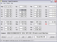
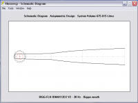
This one is 669 liters tuned to 30 Hz with 97 Db sensitivity @ 1 watt. I wasn't fussy about a super flat response but it was flattening out right away so I took it. I'll sim a bigger one when I get time and decide if another decibel sensitivity is worth the sawdust.
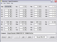
Compression ratio is 2.12:1 and I tightened up the sealed volume some more behind the driver. I am using 18mm for Xmax in all sims now rather than the 24.9mm claim from the company or the 21.9mm claim from the DUMAX.
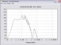
I am simming this one with an 8th order bandpass filter from 22 Hz to 90 Hz. With the filters active it takes about 375 watts to hit the 18 mm excursion limit (123 Db, 2Pi). The last screen shot shows this.


Compression ratio is 2.12:1 and I tightened up the sealed volume some more behind the driver. I am using 18mm for Xmax in all sims now rather than the 24.9mm claim from the company or the 21.9mm claim from the DUMAX.
I am simming this one with an 8th order bandpass filter from 22 Hz to 90 Hz. With the filters active it takes about 375 watts to hit the 18 mm excursion limit (123 Db, 2Pi). The last screen shot shows this.
Attachments
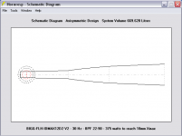

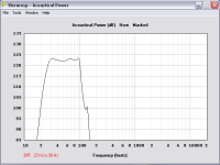
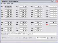
Just for fun I tried the same sim with a bigger mouth (17" x 30") and tightened up the rear chamber some more (to 1.9 cu ft) and well... it flatlined some more, stays above 97 Db all across the band. My copy of Hornresp don't seem to make ripples very well! 😀


Attachments
JAG,
Unfortunately, I have spread the same mistaken information in many of my posts.
I misunderstood RMS as it relates to crest factor, and was also under the mistaken impression that AES2-1984 "watts" are peak, when they are (or should be..) RMS.
1000 watts RMS is equivalent to 1000 watts AES, as a speaker that has met the AES2-1984 specification has withstood peaks four times the RMS rating, 4000 watts. The crest factor has no bearing, since RMS (root mean square) is a measure of average power. A sine wave (3 dB crest factor) of 1000 watts would have the same RMS power as the compressed pink noise (6 dB crest factor) but would subject the speaker to less mechanical stress, as the peak power would only be double the average.
THE AES POWER HANDLING SPECIFICATION AES2-1984 (ANSI S4.26-1984)
Low Frequency Loudspeaker Mounting:
The driver is mounted in free air, oriented so that the motion of the driver is in the horizontal plane.
Test Signal:
The loudspeaker is energized with pink noise, having a crest factor of 6 dB. The pink noise is restricted to one octave, starting at the low frequency limit of the device under test.
Low Frequency Loudspeaker Mounting:
The driver is mounted in free air, oriented so that the motion of the driver is in the horizontal plane.
High Frequency Loudspeaker Mounting:
The driver is mounted on a device which reasonably simulates the acoustical loading of a horn.
Power Calculation:
The RMS voltage at the loudspeaker is measured. The power is then calculated based on the RMS voltage and the minimum impedance of the driver (P=V2RMS/ZMIN).
Duration of Test:
The loudspeaker is subjected to successively higher power levels, with time allowed for the loudspeaker to stabilize at each increment. The recommended stabilization time is 2 hours.
Rated Power:
The loudspeaker is rated for the power that it can withstand for 2 hours without permanent change in acoustical, mechanical or electrical characteristics greater than 10%.
I had also overlooked that the AES rating is free air for loudspeakers, and based on the minimum impedance, which for a free air speaker will be much lower than the average impedance, making the thermal rating higher than it typically would be in a cabinet, and in the case where power compression is noted, it will actually also be underrated.
Although I have long recommended using 1/2 AES power for long term limiting, it was for the wrong reason- if you simulate the free air impedance curve of a loudspeaker compared to it in a cabinet, you will see that it is far higher on average, which explains why even relatively short full power sine wave tests have heated the voice coils enough to smell melting adhesives.
If I had amplifiers capable of the peak power required for the AES test, 6800 watts peak for a B&C 18SW115, the driver would have been just as hot as it was at 1700 watts of sine wave, other than the increased excursion would "fan" out a bit more heat.
Art
As you suspect I did get this information from your posts. So thanks very much for bringing it to my attention. I don't mind being wrong, it allows an opportunity for learning. I'm not thrilled that I didn't notice this myself, especially having copied and pasted the same AES test quote that you did several times.
Anyway, here's some pictures to outline the issue as it's easier to see that way and I did them anyway so i might as well show them.
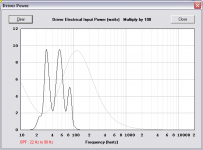
First is OP's driver in IB (IB vs free air with no baffle gives virtually the same impedance and driver power so I chose to show IB instead of free air) vs a small 75 liter sealed box with qtc = .62. Both shown with the same input voltage.

Driver fs is 27.67. The AES test signal would be bandwidth limited from 27.67 hz to 55.34 hz. At fs the IB is drawing about 100 watts less than the small sealed box but at one octave above fs the IB is drawing about 200 watts more.
On average it seems the IB and the .62 qtc draw similar amounts of power when averaged across the octave from fs to 2x fs, they just draw different amounts at different frequencies.
Example 2 - same IB but the small sealed box has been reduced to 33 liters and now has 0.8 qtc. Both shown with same input voltage.

Now the situation is different, the small sealed box is drawing 400 watts more at fs and 275 watts less at 2x fs. On average it looks like the smaller box is consuming more power but the difference isn't a huge amount.
One final example, a different driver in IB vs in a flh with an low knee about an octave above driver fs which is 22 hz. (Bottom graph) Both shown with equal input voltage.

At fs they are both consuming the approximately the same amount of power but at all frequencies between fs and 2x fs the small horn is drawing a lot more power.
So it would appear that I as wrong about AES bandwidth limited signal being 1/2 as intense as a sine wave (RMS). But the difference between measuring consumed power in free air (or IB) vs in any given enclosure would seem to be entirely dependent on the enclosure type and tuning frequency and test signal freqeuncy. The free air driver could end up consuming a lot more than an enclosed driver, or it could end up quite similar on average as shown in the first example. And if tested at only a single frequency it could end up being exactly the same amount of power consumed by both or a difference of several times more for one vs the other depending on the test signal frequency.
Let me know if there's any problems with this analysis.
Last edited:
My copy of Hornresp don't seem to make ripples very well! 😀
I know that's a joke but it's the flare shape you chose that doesn't make ripples very well. And as mentioned that's good if the primary number 1 goal is flat response but maybe not ideal in other respects.
Now might be a good time to start thinking about fold options. A flare like that might not be super easy to fold into the shape you want. Just something to think about.
Interesting indeed! I see that a person (me) can get in trouble quickly not knowing what they're doing. This is my driver with no enclosure compared to the FLH posted above, both at 1000 watts.


I was thinking the same last night about folding a horn this big, just a guy. I think its time to roll out the paper. I'm sure there will be troubles somewhere so this design isn't final until its folded. But if I can fold as simmed I'm gonna love it.
I was thinking the same last night about folding a horn this big, just a guy. I think its time to roll out the paper. I'm sure there will be troubles somewhere so this design isn't final until its folded. But if I can fold as simmed I'm gonna love it.
Attachments
Quick questions... my driver has about 87 Db sensitivity at 1 watt in free air.
Is the 10 Db gain in sensitivity at 1 watt shown in the above horn an average amount of gain considering the 30-100 Hz bandpass?
Depending on the driver can I expect 8-10 Db (or more?) gain from most other types of horn designs (tapped, FLH, or other, etc.) within a similar bandpass and similar size?
Just wondering which horn types tend to show the most sensitivity gain if similarly sized and purposed, basically.
Yesterday was very busy so this thread was mostly ignored, sorry about that. To answer the question about MiniDSP configs, yes as far as I can tell swapping cables is the easiest way to maintain two filter/EQ profiles since each are configured by computer software, per output port, and stored in the unit. Once both profiles are stored though its a simple cable swap. At least thats the way mine works. Newer models may or may not be switch-able, dunno.
I wasn't singling you out anywhere in my rant just a guy, you've been very generous and helpful in this thread and I like you a lot. I like your straight up style presenting information (and disputing as well) too. I'd only be more fortunate if we were neighbors.
I wasn't singling you out anywhere in my rant just a guy, you've been very generous and helpful in this thread and I like you a lot. I like your straight up style presenting information (and disputing as well) too. I'd only be more fortunate if we were neighbors.
Now that I'm neck deep I'm thinking up basics questions right and left, and so far have been able to figure most things out myself after rereading this thread every time I have a question.
But Accoustic Impedance implications as shown in Hornresp are still not clear in my mind, as I don't know if what I'm seeing is good or bad. How are those spikes interpreted by you guys?
Thanks,
Edit: Briefly... please don't spend a lot of time answering these questions.
But Accoustic Impedance implications as shown in Hornresp are still not clear in my mind, as I don't know if what I'm seeing is good or bad. How are those spikes interpreted by you guys?
Thanks,
Edit: Briefly... please don't spend a lot of time answering these questions.
Last edited:
Quick questions... my driver has about 87 Db sensitivity at 1 watt in free air.
Is the 10 Db gain in sensitivity at 1 watt shown in the above horn an average amount of gain considering the 30-100 Hz bandpass?
Depending on the driver can I expect 8-10 Db (or more?) gain from most other types of horn designs (tapped, FLH, or other, etc.) within a similar bandpass and similar size?
Just wondering which horn types tend to show the most sensitivity gain if similarly sized and purposed, basically.
The answers are already here. GM's tapped horn is about 511 liters IIRC, so sim that and compare it to your horn. That will show you sensitivity and you can sim both at xmax (or power max, whichever comes first) and make some educated guesses about which is superior for your goals.
EDIT - the tapped horns posted previously are low tuned of course, so either compare the low tuned tapped horns to one of your low tuned flh designs or redesign the tapped horn with a much higher tuning to compare to your more recent sims. It's all good practice and you really shouldn't decide on a final design until you've played with both flh and tapped horn at least a bit.
Now that I'm neck deep I'm thinking up basics questions right and left, and so far have been able to figure most things out myself after rereading this thread every time I have a question.
But Accoustic Impedance implications as shown in Hornresp are still not clear in my mind, as I don't know if what I'm seeing is good or bad. How are those spikes interpreted by you guys?
Thanks,
Edit: Briefly... please don't spend a lot of time answering these questions.
Acoustic Impedance shows horn throat resistance (black line I assume) and reactance (red line). Other than that I have no idea what's going on with that graph, I don't recall anyone ever giving any kind of helpful description of what it's showing or how to use it, and I never even look at it. (Except just recently in this thread because it seemed like horn throat resistance and reactance might be useful in the reactance annulling discussion.)
Maybe David can help you out on that one.
Last edited:
JAG,At fs they are both consuming the approximately the same amount of power but at all frequencies between fs and 2x fs the small horn is drawing a lot more power.
So it would appear that I as wrong about AES bandwidth limited signal being 1/2 as intense as a sine wave (RMS). But the difference between measuring consumed power in free air (or IB) vs in any given enclosure would seem to be entirely dependent on the enclosure type and tuning frequency and test signal freqeuncy. The free air driver could end up consuming a lot more than an enclosed driver, or it could end up quite similar on average as shown in the first example. And if tested at only a single frequency it could end up being exactly the same amount of power consumed by both or a difference of several times more for one vs the other depending on the test signal frequency.
Let me know if there's any problems with this analysis.
No problems that I see, but when comparing a free-air driver to one in a bass reflex tuned to Fs, the impedance disparity can be large, more than double the impedance average over the pass band for the free-air driver, which would require down grading the AES rating by 3 dB.
Specd,
I have not spent much time looking at acoustic impedance (like none :^) ), as frequency response, excursion, phase response and impedance tell me what I'm interested in.
A 10 Db gain in sensitivity for a 30-100 Hz bandpass is quite good, I doubt you will see much better with a similar size FLH regardless of horn design. Using a more rapid flare at the mouth may increase response at the low knee, but increases excursion and fall off rate below Fc.
A quick model with your driver in a TH of 318 L with a 368 CM horn path at 2 volts is -3 dB at 30 Hz, 95 dB rising to near 100 dB at 70-100 Hz (a narrow dip down to 98dB at 85Hz that may not show up in reality), which IIRC, is near the sensitivity of your much larger FLH design. At 65 volts (around 1000 watts at impedance minima) it puts out from 125 to 130 dB, with excursion of 21mm at 25 and 36 Hz.
As you are learning, similar to working with internal combustion engines, each change of enclosure design has multiple effects, so you must prioritize your goals.
Art
Last edited:
@ weltersys
Hi, i've also been treating AES figures as around half RMS values ! I think a lot of people have too, for many years as well. So Thanx for the LONG overdue clarifications 🙂
You good thing about all this though is, those of us who have operating drivers/systems within the half the AES values, have benefitted from a LOT less thermal compression issues, than we would have running @ towards etc RMS I'll continue to do so
@ just a guy
And Thanx to you for all the additional info etc 🙂
I'll spend some more time on sims over the next few days. I'm interested in knowing more about TH so I'll run off at least a couple of them for study. Then I'd like to reread everything again before rereading everything again that I have bookmarked on folding. Much of it will get printed for personal reference. There is more fun at every turn and quite a few more turns to make... Thanks again guys for your continuing help. The technical stuff is top drawer!
But Accoustic Impedance implications as shown in Hornresp are still not clear in my mind, as I don't know if what I'm seeing is good or bad. How are those spikes interpreted by you guys?
The Hornresp acoustical impedance chart can be safely disregarded when designing a tapped horn. If you would like to better understand the significance of throat acoustical impedance in horn loudspeaker theory, and don't have access to a standard reference text book such as Harry Olson's "Acoustical Engineering" or Leo Beranek's "Acoustics", then the article linked below by Bjørn Kolbrek is an excellent alternative resource.
https://www.grc.com/acoustics/an-introduction-to-horn-theory.pdf
Googling 'throat acoustical impedance' will also provide a wealth of information.
Thank you David, Bjørn's horn primer is great reading! I'm only part of the way through it, but already I would suggest to any newbies to include his introduction into horn theory in their initial reading list. Back to the primer...
Folding Corners: Trapezoid Method
Have the following Trapezoid corner folding method been tried by others? At least a gazillion times by now...?

If so, I haven't read about this yet. I'm going to explain this idea regardless, because I just got all coffeed up abusing calculators and won't be able to sleep for another hour.
I am drawing out the folds for my revised FLH full scale on a 4' x 8' sheet of plywood as spare time allows. As I was preparing to draw out the first 90 degree fold in the horn (and feeling uneasy about poor odds of keeping both the horn path length and increasing volume of the horn correct through the corner), it occurred to me that those path length/increasing volume problems may be solved at once by calculating three Trapezoid shaped sections through that 90 degree corner. After all, thats the obvious sectional shape of the horn seen when looking at a corner, if split into three or more equal sections.
It appears to me that drawing Trapezoid sections through a corner; not only guarantees that the increasing volume of the horn path remains exactly as specified by Hornresp, but also guarantees that segment path length is maintained precisely as Hornresp specifies in the exported file. Because the cross-sectional volumes are being maintained, path lengths are being maintained too. Is this stinkin' thinkin' or is it true?
The Hornresp Schematic export file has all the information needed to make this idea work if each of the "Increment" fields is filled with a number divisible of its respective Segment length, so that each and every section of the segment is equal. Including the last section of the segment which usually isn't equal to the others due to random increments being defined by the user.
Example:
My horn has four segments, each being different lengths. Two are even numbered lengths, while two are odd numbered lengths. They are as follows: 18.42 cm, 121 cm, 119 cm, and 164 cm. The first is short at only 18.42 cm, an even number and won't be folded, but consistent with this exercise lets set its "Increment" field with "9.21" which is 18.42 divided by 2. Next segment is 121, an odd number but easy enough for this example to divide by 10, so "12.1" is entered into that segment increment field. Next is 119 divided by 10 = 11.9, 164 divided by 10 is 16.4. These sectional divisions of each segment may be a bit large for actual folding but this is just a quick and dirty demonstration, so please play along. My horn has an internal Height of 17 inches + internal bracing, so another bracing inch is accounted for in Height = 16 inches, or 40.64 cm as shown like so:

That export results in the following example data:

Using the information on the highlighted line in the above image lets calculate the first Trapezoidal section of a corner using an online calculator. There are several and I'm using this one. Set all three of the Trapezoid calculator fields to use centimeters.
First take the "Height/2 (cm)" figure 20.315893 x 2 = 40.631786 and enter that number into the "Height" field in the online calculator. Next take the Width/2 (cm) figure 5.065000 x 2 = 10.13. Times that number (10.13) x 2 again, = 20.26.
Take that result and split it into two portions, one shorter portion to be entered into the "Bottom Edge" field and the remaining longer portion to be entered into the "Top Edge" field in the online calculator. This example assumes a 1/2 inch wide bottom corner edge so splitting 1/2" three ways (for a three trapezoid 90 degree corner) = 0.166666666667. Enter 0.166666666667 into the Bottom Edge field of the online calculator.
20.26 - 0.166666666667 = 20.0933333333 so enter that number into the Top Edge field of the online calculator. Click the button.
The result (411.60 square centimeter) should match the "Area (sq cm)" field in the Hornresp exported file for that sectional fragment of the Segment being folded if you've repeated this example correctly.
Repeat this process two more times to total the three Trapezoids needed for this 90 degree corner.
This works every time tonight no matter how much more coffee I drink... as long as each horn segment length is equally divided into many sections during the Hornresp export similar to the example above. For 180 degree corners simply add sectional Trapezoids. Angled bends require fewer than three Trapezoids, or more depending on your intended folding angle.
Trapezoid sectioning through corners should result in sectional volumes and path lengths remaining precise throughout each bend and/or corner as each are relational to the other in my stinkin' thinkin' mind.
A folding wizard may be possible (or relatively easy) if all this holds true.
Have the following Trapezoid corner folding method been tried by others? At least a gazillion times by now...?
If so, I haven't read about this yet. I'm going to explain this idea regardless, because I just got all coffeed up abusing calculators and won't be able to sleep for another hour.
I am drawing out the folds for my revised FLH full scale on a 4' x 8' sheet of plywood as spare time allows. As I was preparing to draw out the first 90 degree fold in the horn (and feeling uneasy about poor odds of keeping both the horn path length and increasing volume of the horn correct through the corner), it occurred to me that those path length/increasing volume problems may be solved at once by calculating three Trapezoid shaped sections through that 90 degree corner. After all, thats the obvious sectional shape of the horn seen when looking at a corner, if split into three or more equal sections.
It appears to me that drawing Trapezoid sections through a corner; not only guarantees that the increasing volume of the horn path remains exactly as specified by Hornresp, but also guarantees that segment path length is maintained precisely as Hornresp specifies in the exported file. Because the cross-sectional volumes are being maintained, path lengths are being maintained too. Is this stinkin' thinkin' or is it true?
The Hornresp Schematic export file has all the information needed to make this idea work if each of the "Increment" fields is filled with a number divisible of its respective Segment length, so that each and every section of the segment is equal. Including the last section of the segment which usually isn't equal to the others due to random increments being defined by the user.
Example:
My horn has four segments, each being different lengths. Two are even numbered lengths, while two are odd numbered lengths. They are as follows: 18.42 cm, 121 cm, 119 cm, and 164 cm. The first is short at only 18.42 cm, an even number and won't be folded, but consistent with this exercise lets set its "Increment" field with "9.21" which is 18.42 divided by 2. Next segment is 121, an odd number but easy enough for this example to divide by 10, so "12.1" is entered into that segment increment field. Next is 119 divided by 10 = 11.9, 164 divided by 10 is 16.4. These sectional divisions of each segment may be a bit large for actual folding but this is just a quick and dirty demonstration, so please play along. My horn has an internal Height of 17 inches + internal bracing, so another bracing inch is accounted for in Height = 16 inches, or 40.64 cm as shown like so:
That export results in the following example data:
Using the information on the highlighted line in the above image lets calculate the first Trapezoidal section of a corner using an online calculator. There are several and I'm using this one. Set all three of the Trapezoid calculator fields to use centimeters.
First take the "Height/2 (cm)" figure 20.315893 x 2 = 40.631786 and enter that number into the "Height" field in the online calculator. Next take the Width/2 (cm) figure 5.065000 x 2 = 10.13. Times that number (10.13) x 2 again, = 20.26.
Take that result and split it into two portions, one shorter portion to be entered into the "Bottom Edge" field and the remaining longer portion to be entered into the "Top Edge" field in the online calculator. This example assumes a 1/2 inch wide bottom corner edge so splitting 1/2" three ways (for a three trapezoid 90 degree corner) = 0.166666666667. Enter 0.166666666667 into the Bottom Edge field of the online calculator.
20.26 - 0.166666666667 = 20.0933333333 so enter that number into the Top Edge field of the online calculator. Click the button.
The result (411.60 square centimeter) should match the "Area (sq cm)" field in the Hornresp exported file for that sectional fragment of the Segment being folded if you've repeated this example correctly.
Repeat this process two more times to total the three Trapezoids needed for this 90 degree corner.
This works every time tonight no matter how much more coffee I drink... as long as each horn segment length is equally divided into many sections during the Hornresp export similar to the example above. For 180 degree corners simply add sectional Trapezoids. Angled bends require fewer than three Trapezoids, or more depending on your intended folding angle.
Trapezoid sectioning through corners should result in sectional volumes and path lengths remaining precise throughout each bend and/or corner as each are relational to the other in my stinkin' thinkin' mind.
A folding wizard may be possible (or relatively easy) if all this holds true.
i think a member, Brian Steele has a spreadsheet for folding calculations.
I think that's just for tapped horns, and even then only for one layout.
Have the following Trapezoid corner folding method been tried by others? At least a gazillion times by now...?
None of your images are showing up for me. Even if I "quote" your post and enter the address of the image right into the browser it says "invalid attachment".
I have no idea from your description alone what you are doing.
Folding is not hard but it takes a lot of time, especially if you use advanced centerline.
Volume is not supposed to be exactly the same as the sim going through the corner, this is why we add 20 - 25 percent to sims to account for wood and extra space in fold corners. As you can see in this old pic of a reverse engineer of an existing folded design from soho54, the corners in the actual folded plans flare out at the folded corners in a way that the sim doesn't reflect.
This is ok, the volume in the corner SHOULD be a bit more than in the sim and it will all work out fine. You could sim all these corners properly but it would have to be done in Akabak with a LOT more segments, but it won't make any big difference anyway.
Now I mentioned that I had some folding tips and tricks that can make things easier. The biggest tip is this:
Any PAR segment that is folded back on itself will create a perfect rectangle (or square) if two sides of the box are parallel. Any partial PAR segment that is folded back on itself will create a perfect rectangle (or square) in the folded portion.
That's pretty good news as it means that you can treat entire segments as rectangles which makes it a LOT easier to fold the folded rectangular segments into a rectangular box.
If S2 is set to Auto in the wizard, then the first two segments can be treated as one single segment, as the expansion rate is the same and there's no flare rate discontinuity at S2.
Tip 2 - The length of any folded segment is going to be approximately half of it's unfolded length (assuming it's folded exactly in half). That can save a LOT of time in layout. Just fold your segments into perfect rectangles half as long as they would have been if they were straight. This isn't perfectly accurate and can be played with later (either change the sim to reflect the actual length or change the fold to reflect the simulated length).
Using these two tips alone you can get a rough fold done in a few minutes. This would require a bit of forethought in the sim process to make the segments a length that would facilitate this process, but it's not hard.
If you want to use advanced centerline method and don't use these tips you could end up folding your oddly shaped flare into a rectangular box for weeks before you get any success, and the shape of the flare might NEVER be suitable for folding into a rectangle no matter what you do or how much time you spend.
I'm not going to talk about snailshell folding (where the path circles a center point like the Labhorn) since this won't work with your sim.
Anyway, good luck and have fun with it. You might have to change your sim into something that can be easily folded (or folded at all) but it's all part of the fun.
- Status
- Not open for further replies.
- Home
- Loudspeakers
- Subwoofers
- FLH design basics for a dummy