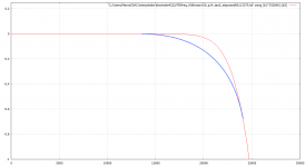
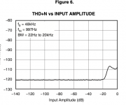
Why is distorsion increasing when signal is above -20 dBfs for the PCM4222? Is it the analog front end?
//
//
Attachments
Last edited:
Probably. It could also be noise modulation, but I would guess it is mainly distortion of the analogue part of the PCM4222.
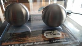
Found like a miracle the last 3 halfs for making the spheres. I have at least 15 boxes in the basement but managed to open the right one first 🙂
Fedex says the regulators is here within a few hours. Postnord - the big post company here is taking a lot of time to handle customs...
FPGA boards are in transit and "Arrived at Transit Hub"... this may take time..
//
Fedex says the regulators is here within a few hours. Postnord - the big post company here is taking a lot of time to handle customs...
FPGA boards are in transit and "Arrived at Transit Hub"... this may take time..
//
Attachments
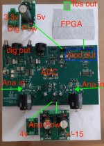
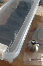
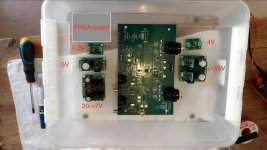
So here is a first stab at layout in the ADC-box. Fits on top of a A4 sized paper.
//
//
Attachments
Last edited:
Capsules arrived. Sent in a soft envelope with puny bubbel plastic. Aren't these precision devices...?
Found a good box for the batteries.
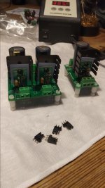
Now for some soldering of the regulators. Need to dive into the basement again as I typically didn't manage to order the right things from ldovr. Note to self - don't do internet shopping after midnight! Its the 8v feed that is not provided for... but I do have good substitutions.
I would have liked to see that the grommet had an inner grove to fixate the capsule - there where just a clean straight wall. Also, the rubber was quite hard...
//
Found a good box for the batteries.
Now for some soldering of the regulators. Need to dive into the basement again as I typically didn't manage to order the right things from ldovr. Note to self - don't do internet shopping after midnight! Its the 8v feed that is not provided for... but I do have good substitutions.
I would have liked to see that the grommet had an inner grove to fixate the capsule - there where just a clean straight wall. Also, the rubber was quite hard...
//
Attachments
Last edited:
Thanks - needed 🙂
The circuit you designed is the challenge in the sense that it need to go into the small spheres. But I can test the EVM board. I wonder if the EVM is sensitive / could be broken if one add the +/-15 volt before the 5V etc.. Is there a need for orchestrated power on...?
Better consult the manual 🙂
//
Should do you think the metallic body of the capsule (ground) be galvanically connected to the metallic sphere body of the mic to be?
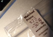
Matched pair! Spec says -37 +/-3 dB... uhu... 4 dB off - what....??
//
Matched pair! Spec says -37 +/-3 dB... uhu... 4 dB off - what....??
//
Attachments
Last edited:
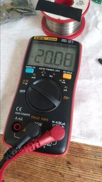
Got the charger. Its labeled 21V, 1,5A. Charged a batterie and it went form 18,4 to 19,5 in 30 minutes. 1 Hour charging gave 20,5V.
This is a bit of a problem as the max voltage of the 3045 boards are 20V. Thinking of the function to switch in/out a rectifier bridge to manage 0,7V....
I really don't know when the BMS in these batteries will switch off... need to deplete one to find out. Maybe it is the specified 18V - probably...
//
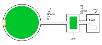
OK. I'm thinking maybe to build one large Faraday box of the whole recording system incl. batteries. Shielded cables for power, metallic box for batteries /double isolated with inner plastic cage - se post above... Mic box metallic. Signal / power to mics shielded cables.
So, the red little lug from capsule to sphere - there or not -
- connected: anything radiated is galvanically transfered into the system - Capsule body = ground....
- not connected: a "big" opening in the cage... but the cage as an antenna is not connected to ground....
Details are fun! But not necessarily meaningful.. 🙂
//
Attachments
Last edited:
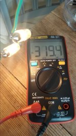
So I drained one batteri until it would not lit the bulbs anymore. One was suppose to draw 5W at 24V but it seem to consume more so I connected both that came in the package - that yielded 320 mA - good enough...
Time U I
14.15 20,1 0,32
15.12 19,7 0,32
17.15 18,9 0,31
19.55 18,2 - but it worked just a minute before...
so 5,5 hours at 320 mA but the consumption will be around max 250mA/batt so plenty enough and I don't need to charge to more than to 19,5V which will be OK for the stabs that only do max 20V - I will still get > 5 hours. Long recording sessions no problems...
//
Attachments

Or you could charge them fully, then slightly drain them ('dummy' load, or some such) before use. I don't know about lithium, but NiCd and NiMH don't hold their charge-complete voltage for more than a couple seconds after disconnecting the charger. Then whatever the voltage settles to, open-circuit, it'll quickly drop another ~10% within seconds of applying a load --even a light one, anything over about C/20.
Maybe just see what the open-circuit voltage is an hour after removing from the charger .. or a minute into a 50mA load. 😀
Cheers
Maybe just see what the open-circuit voltage is an hour after removing from the charger .. or a minute into a 50mA load. 😀
Cheers
Last edited:
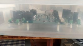
Mounted the ADC box stuff in a temporary (? 🙂) box. The whole thing became considerable larger than I had envisioned... this is not something that you hang on the stand, close ro the mics. Cables from the mics have to be at least a meter, maybe 2, longer than I had hoped for. Well well 🙂
//
//
Attachments
Last edited:
Still, I would have liked to be able to keep track of the voltage per batteri. But I don't like to use these digital display meters due to the potential noise injection... but they look nice and have an attractive price...
On the other hand, analog panel meters show 0-30V but the reading will be to hard as this is about keeping track of 19,7V -> 18,3V ... is there a trick to "amplify" the scale in an easy, non active, way? 🙂 I would have liked a 15-25V VDC panel instrument but they all seem to start a zero....
Heschen Rektangular voltmeter analog panel volt spanningsmatare 670 stil DC 0–30 V klass 2.0 : Amazon.se: Industriella verktyg & produkter
ARCELI 0,56 tum DC 0–30 V digital voltmeter spanningstestare matare ljus LED-skarm 3 tradar Volt matare for motorcykel bil motorpanel montering – bla : Amazon.se: Bygg, el & verktyg
//
Are these pin assignments OK? I tried to keep active digital signals close to ground pins.
Inputs:
NET "wck" LOC = P50; // L31N_2, pin 6 of SV2
NET "mck" LOC = P51; // GCLK input, L31P_2, pin 5 of SV2 (right next to ground)
NET "mod[6]" LOC = P40; // L64N_2, SV2 pin 8
NET "mod[5]" LOC = P41; // L64P_2, SV2 pin 7
NET "mod[4]" LOC = P34; // L1N_3, SV2 pin 10
NET "mod[3]" LOC = P35; // L1P_3, SV2 pin 9
NET "mod[2]" LOC = P32; // L2N_3, SV2 pin 12
NET "mod[1]" LOC = P33; // L2P_3, SV2 pin 11
Switch to select between four high-pass filter options (autocalibration and second-order Butterworth at 1.2 Hz, 4.8 Hz and 9.7 Hz):
NET "hpsel[3]" LOC = P138; // L4P_0, SV2 pin 41
NET "hpsel[2]" LOC = P140; // L3P_0, SV2 pin 39
NET "hpsel[1]" LOC = P142; // L2P_0, SV2 pin 37
NET "hpsel[0]" LOC = P144; // L1P_0, SV2 pin 35
I2S output:
NET "lrck" LOC = P66; // L2N_2, SV1 pin 10
NET "bck" LOC = P57; // L14N_2, SV1 pin 8
NET "i2sdata" LOC = P58; // L14P_2, SV1 pin 7
Debugging LED:
NET "fclipled" LOC = P123;
// LED9 on the Mojo version 3
- Home
- Source & Line
- Digital Line Level
- Fixed gain field recorder?