You could put a 12V and a 5V zener in series with 0-5V meter. It might take a little fiddling with some parallel resistors to finesse bias and leakage currents, but it would give the 'expanded' indication you want.
Regards
Regards
Wouldn't it be more convenient to put two run-of-the-mill LDOs that can handle 25 V between the batteries and the low-noise regulators? Just let them regulate down to +/- 18 V and go in dropout when the battery voltage is too low to reach +/- 18 V. Of course you can still add an indicator to check the battery voltage, but at least you can normally charge the batteries then.
Yes a pre-regulator to be able to use them fully charged would probably in the end give so much run time that I do not need to have any meters on them. And if it turned out that it would be good, I could probably allow myself to put these cheap ones "north" of the pre-regulators which would probably filter out most of any dirt before the main ones. Jepp - 3 regulators that do 18V and can take say 25. Dont have to be to fancy regs really.
//
//
Indeed. Besides being able to handle the voltage, the main requirement is a low dropout voltage.
Does the 3rd leg of those 3-terminal regulators stop drawing current as they approach dropout? A 10 ohm resistor and comparator could light a LED when they're no longer regulating.
BTW, I don't think there will be much dirt coming from the Li-ion batteries -- they're probably quieter than most sources.
Cheers
BTW, I don't think there will be much dirt coming from the Li-ion batteries -- they're probably quieter than most sources.
Cheers
The batteries BMS goes inte hard current limit it seems when I tested above and the batt approched 18,2.
The dirt I'm worried about is what may come out of these: ARCELI 0,56 tum DC 0–30 V digital voltmeter spanningstestare matare ljus LED-skarm 3 tradar Volt matare for motorcykel bil motorpanel montering – bla : Amazon.se: Bygg, el & verktyg
Thanks for all suggestions and hints - appreciated.
Marcel, I think the pin assignment is fine. I suppose it would be possible to change if for some reason it would be beneficial?
What kind of switches do I need - bounce or make?
//
Just a simple rotary switch with four positions should do, it doesn't even matter whether it is break before make or make before break. The common contact has to be grounded. The pin assignment can indeed be changed, although there are some limitations on where mck can be put.
Attached is my first attempt to come up with a configuration file for the FPGA. It is likely to be full of bugs, as I haven't simulated or tested anything yet. At least it fits in the FPGA and meets the timing, assuming the FPGA has speed grade 2. The FIR filter and CIC filter were generated with Xilinx FIR compiler 5.0 and CIC compiler 2.0, respectively.
I haven't figured out how to directly generate a .bin file. It is claimed on several reliable-looking websites that you can just take the .bit file and delete the header before the row of FFs, so that's what I did.
Attachments
Last edited:
Your efforts are very much appreciated Marcel. It will be some time before we can test this but I'm looking forward to it. I'm in re-location state which makes things a bit harder but I will keep this up as I "move along".
I will look for a switch and post a link for scrutinisation 🙂
//
I will look for a switch and post a link for scrutinisation 🙂
//
I just simulated the IIR high-pass filter and as expected, found a couple of bugs. The weirdest one was that I had a big crosstalk between the left and right channels of a digital filter. Anyway, they are fixed now. Next thing will be simulating the whole path.
I fixed all the bugs that I could find by reasonably short simulations, included a clipping detector and improved the constraints a bit. I think you have a good chance that this will work, see the attachment. The .bin file should be all you need, but I included the source code for completeness and for anyone who might be interested.
LED9 is used as a clipping LED now (the ones on the evaluation module don't work with an external digital filter). You can connect an extra LED with its own 330 ohm series resistor in parallel with it if you like, using connector SV2 pin 50.
LED9 is used as a clipping LED now (the ones on the evaluation module don't work with an external digital filter). You can connect an extra LED with its own 330 ohm series resistor in parallel with it if you like, using connector SV2 pin 50.
Attachments
Maybe you can better wait with posting it. If the configuration file from post #251 works as intended, I won't even need the board. If it doesn't, then it may be handy for further debugging.
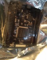
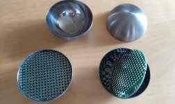
Made the boards for the spheres. Drilling the 12mm hole for the capsule will be a bit of a challenge for me with very limited metal craft tools etc... this is stainless... I got soic adapter boards to manage the OP-amps...
Parcel to Marcel 🙂
//
Parcel to Marcel 🙂
//
Attachments
Last edited:

- Home
- Source & Line
- Digital Line Level
- Fixed gain field recorder?