These are for case 2:
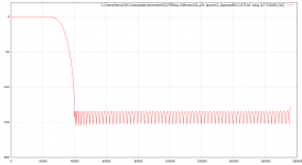
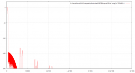
Magnitude in dB versus frequency in Hz
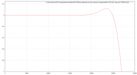
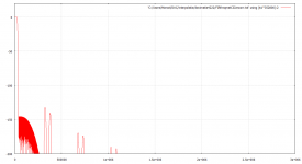
Zoom of the same
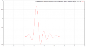
Impulse response, x-axis unit is sample times of 1/352800 s
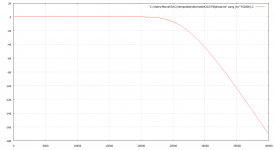
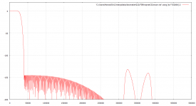
Deviation from linear phase in degrees versus frequency in Hz
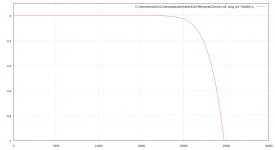
Zoom of the deviation from linear phase
Magnitude in dB versus frequency in Hz
Zoom of the same
Impulse response, x-axis unit is sample times of 1/352800 s
Deviation from linear phase in degrees versus frequency in Hz
Zoom of the deviation from linear phase
Attachments
-
 FIRfreqWilkinson160_352kHz8_taumin15.png40.7 KB · Views: 128
 -
 FIRfreqWilkinson160_352kHz8_taumin15_zoom.png31.1 KB · Views: 129
 -
 ImpulseWilkinson160_taumin15.png37.3 KB · Views: 128
 -
 Deviationfromlinearphaseindegrees_Wilkinson160_taumin15.png30.1 KB · Views: 125
 -
 Deviationfromlinearphaseindegrees_Wilkinson160_taumin15_zoom.png30.1 KB · Views: 121
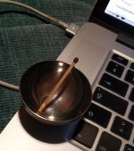
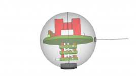
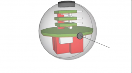
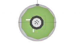
I think I can fit the Marcel circuit into a sphere made out of stainless steel from IKEA with a diameter of 50mm.
See the attached .mp4 video...

//
See the attached .mp4 video...
//
Attachments
Last edited:
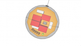
How about this one?

//
//
Attachments
Last edited:

Yes I'm not surprised - I wasn't hoping for unique 🙂
Thanks, want to read about that one!
//
Some quotes I found..
Neumann's KK50 capsule assembly
"Through the design of mounting the Omni-directional capsule within a spherical housing, whereby the diaphragm almost becomes a small percentage of the surface of the sphere, helps to obtain the characteristic sound the KK50 capsule gives us. Somewhat similar in principle to recent the B&K microphone and "slide on" ball combination.
Let us not forget the old ST&C 4021 "Apple (Ball) and Biscuit" dynamic model, whereby the diaphragm also sits on the surface of a sphere. However, the "Biscuit" forms a screen to direct high frequencies, therefore enabling the microphone to offer an omni-directional pattern across the whole frequency spectrum."
Here, post #4: seems a bit promising re to the casing shape...
DIY M50 capsule | GroupDIY
Post #661
"Eyeball" capsules
This e.g., sound interesting to me:
"The degree of this effect can be quite surprising--I remember being in the control room of a large studio when recording a string quartet, and feeling a strange cognitive dissonance between what I heard through the monitors and what I saw through the glass: The quartet sounded as if it was being recorded from a moderately close perspective, but the M 50s were 20 feet or more (6 - 8 meters) away, up fairly high on stands. No clear recording should ordinarily have been possible at that miking distance.
When microphones can be placed more distantly from, for example, a large orchestra, this helps to solve one of the basic problems of recording a large ensemble in a concert hall: Concert halls are generally designed to have the proper reverberation balance when they are mostly full, but recordings are generally made when the hall has no audience in it; thus the microphones have to be brought in closer to the ensemble to avoid an overly reverberant pickup. But then some of the players will be (proportionately) much closer to the microphones than other players are, and will thus be picked up far more strongly and distinctly."
Pano had the right answer on ball effect! 🙂
///
Last edited:
How about this one?
//
Both of them give the same error on the Android device I used yesterday and work fine when I look at them with my Linux computer.
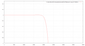
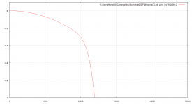
With the Xilinx program I have (free version of ISE 14.6), I can easily generate CIC filters up to the sixth order. Cascaded with Wednesday's linear phase filter, I get the attached frequency response (horizontal axis in Hz, vertical in dB). There is no need for intermediate rounding between the filters and it looks like it still fits in an XC6SLX9, the second smallest Spartan 6 FPGA.
The suppression around 300 kHz doesn't quite meet your spec: only 132.6713828 dB at 324.6173 kHz instead of 140 dB...150 dB, and it is bound to get a few dB worse when I compensate for the droop in the passband. The analogue filter on the evaluation module only cuts off above 657.3979 kHz (theoretical value, obviously), so that won't help. Then again, any practical microphone will have rolled off more than 20 dB at 300 kHz, so you will still meet it from acoustical input to digital output.
I assume there is no need for a digital high-pass filter, as you can remove the offset (which will be large, -20 dBFS or so) and any subsonics in your DAW. Is that a correct assumption?
Attachments
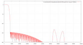
The suppression of aliases around 300 kHz only degrades to 132.1246 dB at 324.5484375 kHz, so less than 0.55 dB degradation, when I include a five-tap correction for CIC filter roll-off. The in-band response becomes much flatter, as it should.
Attachments
Cool! -140dB was not grounded in any deeper insight - I'm sure -132 is perfectly fina too.
Can I get one of these, program it and interface it (from and back) to the EVM?
https://www.ebay.com/i/332711086694...MIvM6i3sS18QIVEq-yCh2IPQLCEAQYAiABEgJJHvD_BwE
How is the ouput
//
Can I get one of these, program it and interface it (from and back) to the EVM?
https://www.ebay.com/i/332711086694...MIvM6i3sS18QIVEq-yCh2IPQLCEAQYAiABEgJJHvD_BwE
How is the ouput
//
Eventually, yes. You would need a JTAG programming cable and a free program from Xilinx for that.
There are some things I would need to do first, though: add a dithered rounding stage to reduce the output word length to 24 bits (it's sixty-something bits now), instantiate a clock multiplier, add some glue logic, add an output interface, run synthesis and implementation and fix any bugs, and provide you with a configuration file.
If an I2S output is OK (which means you need a DIT (digital interface transmitter) chip to interface it to your optical transmitter), then it's mostly a matter of reusing stuff I wrote for my valve DAC project.
Have you found a datasheet, user manual or schematic for that module? If so, can you post a link?
Last edited:
Sounds like a lot of job... But if you would consider doing this to help me I would buy and ship a board to you - at least 😉
Maybe this board:
1X DIY FPGA Development Board Module Spartan 6 XC6SLX9 for Arduino | eBay
is actually the same as: (NB: Documents tab..)
Mojo v3 FPGA Development Board - DEV-11953 - SparkFun Electronics
OK! I would need a i2S to toslink board! No prob.
//
Maybe this board:
1X DIY FPGA Development Board Module Spartan 6 XC6SLX9 for Arduino | eBay
is actually the same as: (NB: Documents tab..)
Mojo v3 FPGA Development Board - DEV-11953 - SparkFun Electronics
OK! I would need a i2S to toslink board! No prob.
//
It certainly looks the same, and I think it would be very suitable.
That Mojo v3 board can be programmed without a JTAG programming cable when you use the Alchitry software like Mojo Loader (see Getting Started With the Mojo | Alchitry ), which is nice because a JTAG programming cable can easily cost 50 euros. It's also nice that it uses series regulators rather than buck converters, which avoids some potential interference issues.
That Mojo v3 board can be programmed without a JTAG programming cable when you use the Alchitry software like Mojo Loader (see Getting Started With the Mojo | Alchitry ), which is nice because a JTAG programming cable can easily cost 50 euros. It's also nice that it uses series regulators rather than buck converters, which avoids some potential interference issues.
Cool. I see the 8 output pins from the EVM but which inputs shall these go to on the Mojo?
And where would the i2s come out?
And some good proper (opto) isolation between the EVM and the Mojo... and yet one battery / 5V system.
//
And where would the i2s come out?
And some good proper (opto) isolation between the EVM and the Mojo... and yet one battery / 5V system.
//
Attachments
Last edited:
The inputs and outputs will be at whatever pins are specified in the user constraints file that I will write, although the master clock MCKO can only be connected to special clock pins.
Do you have a preference for certain pins?
Do you have a preference for certain pins?
Hi! OK and not at all.
I'm thinking of a "long(er)" box with the EVM in one end and then maybe this in the other so wiring should be opposite side to the i2s maybe in order not to have to route cables "backwards" in the box... a natural signal flow in one direction would satisfy my almost sick need for structure :=)
Would you be helped using one such board? If I order I can get two and send you one which you of course can keep.
If that special cable is not needed - what type i/f do one use between computer and board in order to program it? I have quite limited experience with this... My comps are Macs but I do own an old laptop running W10 I think...
//
Programming is done via the USB interface using the Mojo Loader program I linked to in post #195, but as I never used such a board, I'm not familiar with the details. Mojo Loader requires a *.bin file, which I can generate with the Xilinx programs. It looks like Mojo Loader is for Windows and Linux, but not for Mac.
It could be handy for debugging if you sent me a board, depending on how much will go wrong. If there's not too much going wrong, we can also just send *.bin files and observations back and forth via this thread until everything works properly.
It could be handy for debugging if you sent me a board, depending on how much will go wrong. If there's not too much going wrong, we can also just send *.bin files and observations back and forth via this thread until everything works properly.
- Home
- Source & Line
- Digital Line Level
- Fixed gain field recorder?