I have managed to successfully do smd soldering. I have also failed 🙂 ... with two irons its doable...
How about batteries... 2X 18V 3000mAH is my idea.
NI-MH OK? It might be a good idea to buy into a specific product line... like Makita Tools..
2 batteries and a (double) charger. But how to interface such batteries when to feed the recording system?
//
How about batteries... 2X 18V 3000mAH is my idea.
NI-MH OK? It might be a good idea to buy into a specific product line... like Makita Tools..
2 batteries and a (double) charger. But how to interface such batteries when to feed the recording system?
//
So tool batteries are 14,4 and next is 18v. My regulators only do 20v in but a 18V NI-MH is 21V fully charged. Remains 14,4... fully charged -> 17V... dropout for the 15V supplies are about 0,3V so the range will be 17->15,3... 1,7V (should have been 17-14,4=2,6V)
How much of say a 3500mAH battery will I get out of this? 1,7/2,6*3500=2300 ??
//
How much of say a 3500mAH battery will I get out of this? 1,7/2,6*3500=2300 ??
//
I dunno. Can you just use 9V batteries to get it up and running and tested? The eval board will run OK on +/- 9V won't it?
It could. And I think it will work. And I do have work bench resources - no problem.
I'm aiming for the end-game 🙂
//
I'm aiming for the end-game 🙂
//
Indeed! But wow, just how much capacity do you need? My Zoom and TASCAM recorders run for hours on 4AA cells.
I realise I made som error in my power budget when you put the question out 🙂
The energy budget:
The EVM board:
2x200mA @ +/-15V
200mA @ 5V
=> 600mA
Mic-board: 10mA (?) x2 => 20mA
0,61+0,02 = 0,63A + losses => 0,7A (?)
4 hour recording: 0,7x4=> 2,8AH @ 14,4-17V …
3500mAH -> 5 hours.
The EVM is a bit hungry...
//
The energy budget:
The EVM board:
2x200mA @ +/-15V
200mA @ 5V
=> 600mA
Mic-board: 10mA (?) x2 => 20mA
0,61+0,02 = 0,63A + losses => 0,7A (?)
4 hour recording: 0,7x4=> 2,8AH @ 14,4-17V …
3500mAH -> 5 hours.
The EVM is a bit hungry...
//
Last edited:
Maybe the 200mA are max figures... or source capacity requirement. Manual don't say really.. Typically varies with Fs... google...
//
//
Last edited:
With a separate battery for the negative supply, the current from the positive supply is 200 mA less than you estimated. Do you still intend to make your own decimation filter eventually?
200mA each side does seem like a lot, but perhaps it just isn't optimized for battery use.
It should be easy enough to measure, right?
It should be easy enough to measure, right?
Its probably performance optimised - perfect for me. I don't mind the battery need really - it will be OK. I'm in the mindset to go (almost) all in with this system. I purchased LT3045 based stabs for all 10 involved voltages - I don't know if it could perhaps be done cheaper - but I don't want to worry - I took (almost) the best.
//
//
Last edited:
With a separate battery for the negative supply, the current from the positive supply is 200 mA less than you estimated. Do you still intend to make your own decimation filter eventually?
EVM manual says 200mA for all these... +15, -15 and 5v... But yes - a 3rd battery is perhaps a good idea... for more than one reason...
I wonder what the average consumption is... I have to find out really...
I asked TI forum 🙂
I would really like to do <0,499*Fs filters but I think it will have to wait for the FREX ADC which I still want to own. It has that capability.
I cant even envision a solution... an external DSP etc...?
//
Last edited:
The PCM4222 has a feature that it can output the raw multibit sigma-delta modulate. You can then for example use an external FPGA module to do the decimation filtering.
I have no experience with DSPs, that's why I always suggest FPGAs. Basically anything that's Turing complete, has enough memory and is fast enough can do the job, but I haven't a clue if DSPs are fast enough.
I have no experience with DSPs, that's why I always suggest FPGAs. Basically anything that's Turing complete, has enough memory and is fast enough can do the job, but I haven't a clue if DSPs are fast enough.
Aha... but its way above my ability anyways I'm sorry to say. DSP or FPGA... I can do a FIR coefficient file 🙂
//
//
It would have been Turing's 109th birthday today, by the way. Unfortunately he died at the age of 41 due to cyanide poisoning (either suicide or a freak accident).
Anyway, in late 2017 someone with user name tfmoraes intended to design a decimation chain for an AT1201 ADC using an FPGA. If he succeeded, maybe he came up with something that can be easily adapted for your needs. If not, if you are not in a hurry and if the preliminary results with the built-in filters are neither so bad that you stop the whole project nor so good that you don't want a separate digital filter anymore, I can try to come up with something.
Anyway, in late 2017 someone with user name tfmoraes intended to design a decimation chain for an AT1201 ADC using an FPGA. If he succeeded, maybe he came up with something that can be easily adapted for your needs. If not, if you are not in a hurry and if the preliminary results with the built-in filters are neither so bad that you stop the whole project nor so good that you don't want a separate digital filter anymore, I can try to come up with something.
Cheers Turing!! A real enigma... 😉
Cool - thanks - a bunch!!
It annoys me to no end that the industry has not understood the sampling theorem. (Actually I think they have but the darn Product Managers just want to beef up the spec sheets with the absolutely highest FR possible). No energy equal or representing Fs/2 shall go into the sample&hold function. This means that your product (yes, I'm talking to the tech companies🙂) will not produce Fs*0,5 at -0,000000001dB - the guard band must start at Fs*0,45 and not Fs*0,52. Have hard can it be? Wow, that gave my digestion system a kick start in the morning 😉
I'm quite sure this will sound very good. I will not be able to judge if there would be any improvement with a steeper filter but I would like to trust science and build something theoretically correct and see where that leads. I'll bet/guess it will be superior.
And I will eventually also use a low phase noise clock 🙂 again, for purely theoretical reasons - I'm not at all certain it matters in reality. (Almost) all in!
//
Last edited:
Actually, I'd like my guard band to start at Fs/4 using probably 88Khz Fs. So drop off (-0,1dB) starts at maybe just above 20k... Wanted position for me and my recordings. So if it was possible to cheat the filter to think that they are at Fs 44,1 but in fact the sampling is going on att 88 would be nice but the TI forum answered that it is not possible to configure that. Then in my preferred realisation my filters would be less steep starting at Fs/4 to reach a stop-band at -140 dB for Fs*0,4999 🙂
//
//
Last edited:
Digi-Key bags on the table. I must say that the shipping US-EU is speedy. When did I place this order... hmm...
39 hours door-2-door....
//
39 hours door-2-door....
//
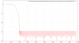
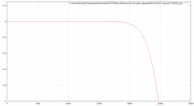
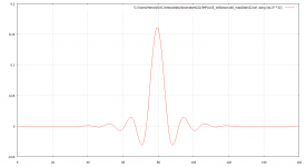
Regarding the last decimation step, what would you prefer:
1. No peak in the response, perfectly linear phase, equal pre- and post-ringing
2. A slight response peak, nearly linear phase over the passband, somewhat reduced pre- and somewhat more post-ringing?
Attached are pictures for case 1:
Magnitude in dB versus frequency in Hz
Zoom of the magnitude
Impulse response, horizontal axis in 1/352800 s sample times
Attachments
Last edited:
- Home
- Source & Line
- Digital Line Level
- Fixed gain field recorder?