Damn, a blast from the past, the last time I used the chain rule was in physical chemistry
Ihquam you’re the man
Ihquam you’re the man
Papa is using Bench Modelling
Rest of us, Sissies
Well, except lhquam, he knows Math

Speak for yourself.
I survived the plasma equations... I'm sure Nelson did too.
Hey... that was my Dodge... where did you get that picture? That was us coming back to the States from crashing the frats at UBC during Easter break in '80.
Man, Bernie and Byron are gonna be mad....
The Border Patrol guy asked us:
"Anything to declare?"
"No, nothing".. I said
"So what are those? " pointing to a carton of smokes on the dash that Jim forgot to stash away...
It was a true Northwestern Cheech and Chong hour while they held us for "inspection". Thankfully they never inspected the car.. we had boats loads of good Canadian beer and smokes.
🙂
BTW: I had a Pioneer cassette on that car.
Last edited:
Thank you very useful, when I finished calculating next year ......Here are some useful equations for the Roctacher SPICE model:
View attachment 1414704
:--))
The Adcom will be a stereo version, the other 4 heatsinks will be used for 2 monoblocks 🙂
For now I have only one front end but I will draw another pcb with a different one.

For now I have only one front end but I will draw another pcb with a different one.
Relieved from elevator or plasma-cutting duty(?) these just arrived from Pras:

I am planning to change my F5- which has a real turbo power supply - into a F5 SIT by using the board as input driver (*10) and connecting the SIT/follower as output. Re-consign it is I think . .
About the PS: it is of course symmetric, +/- 25V, runs with 4 pairs of parallel 2SK175 / 2SJ55. So one set will be the driver; the 2SJ55 already there to be the SIT-follower ; the SIT being a 2SK180 or so. makes it simple to do.
I have to puzzle how to use the symmetric PS in the new configuration where the old V+ becomes the earth. Any ideas? It implies part of the PS is balanced (floating..). I have a vague idea that if needed I can use a transformer coupling to overcome the power line structure,

working on the complex scheme.
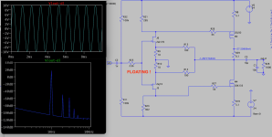
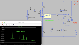
INPUT driver = F5 with laterals. At about 20Vpp output this is -60dB 2ndH. The power supply is a standard transformer and bridge giving a centre tapped 'earth'. The loading of the output is interesting. Furthermore, one can play around slightly and get some influence on the harmonics.

Then the output stage, with a proxy system to get the correct bias. A 'voltage shifter' should work too, but hey, this is automatic. At about 15W this is with a 2nd H at -45dB.
= Generg might call it 'Muffy', for me it was simple to understand and bring together..

So the question is: can I just use the front-end like this (no direct ref to the common terminal of the power supply!! - just ref to a virtual earth on input), and connect that to the output stage that has its ref to the now official ground?
------
Because I have this case ready I'ld like to use it. The biggies on the back are rated for 25V. I have one + and one - per channel. I thought to keep it and connect the speaker to this point, because it will give such nice sparks if I just push the LS wire against the case instead of in the correct terminal. [I know I need precautions then, better is to have a separate electrolytic...]

Why change?
The sound of the F5 with laterals as I have it, is just a bit too 'forward' compared to my 2SJ28 V-FET implementation.
And my 2SK182 with choke in the drain is just a bit too warm or less suited to 4Ω maybe.
INPUT driver = F5 with laterals. At about 20Vpp output this is -60dB 2ndH. The power supply is a standard transformer and bridge giving a centre tapped 'earth'. The loading of the output is interesting. Furthermore, one can play around slightly and get some influence on the harmonics.

Then the output stage, with a proxy system to get the correct bias. A 'voltage shifter' should work too, but hey, this is automatic. At about 15W this is with a 2nd H at -45dB.
= Generg might call it 'Muffy', for me it was simple to understand and bring together..

So the question is: can I just use the front-end like this (no direct ref to the common terminal of the power supply!! - just ref to a virtual earth on input), and connect that to the output stage that has its ref to the now official ground?
------
Because I have this case ready I'ld like to use it. The biggies on the back are rated for 25V. I have one + and one - per channel. I thought to keep it and connect the speaker to this point, because it will give such nice sparks if I just push the LS wire against the case instead of in the correct terminal. [I know I need precautions then, better is to have a separate electrolytic...]

Why change?
The sound of the F5 with laterals as I have it, is just a bit too 'forward' compared to my 2SJ28 V-FET implementation.
And my 2SK182 with choke in the drain is just a bit too warm or less suited to 4Ω maybe.
Last edited:
lets go in steps
PSU question first
for second, see ACA Mini article, single rail
and remember - GND is, in most cases, state of mind
so easy to jingle
PSU question first
for second, see ACA Mini article, single rail
and remember - GND is, in most cases, state of mind
so easy to jingle
I never really fooled with temperature behavior in the model. I just never needed to. I suppose you could do something simple with a temperature dependent resistor in a sub circuit model if you really need to approximate something.
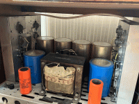
Indeed, ACA is a great idea, gives a great sonic imprint if I'm correct t - and of course I have it laying around prbably, but where??, like a lot of phools 😏 who have more drawers and bins than shelves in the main room.ZM. My F5 PS: simple bridge, two windings. True bifilar. Common is now earth. Connected to first 4.700uF (red), then 0,2Ω to 10.000µF (blue) then another 0,2Ω to final 27.000µF (yellow in the picture) for a split +/- per channel.
I'm up and running. Sounds great! Very dynamic sound. I'm using the FQA 36P15 with the THF-51S.

This follower stage represents my version of the trial given by Nelson, with some assistance from Lynn. It's not a FW SIT-5, it just uses the trick that Nelson discussed with the output caps.
- Home
- Amplifiers
- Pass Labs
- First Watt SIT5


