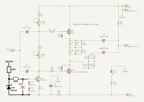
Hi Botte, I see -37.7V at the drain of the J113 and 56.4V at the source, so only 19V to endure for poor J113.
What do you think?
What do you think?
It will be pulled to the ~top rail( - Bias) when the signal goes there. So from an AC standpoint over the 35V
- J113 is just a sim part. Of course any other will work with a higher Vds max - it is just a CCS. I have used the 2SK30AGR with a Vb of 50v. More sturdy jFET? 2SK373 @ 100V. Maybe go real. DN2540 etc. That will not break. MPSA06 is great with its 80V but it looks like a BJT.
- R15 in combination with the DC output of the buffer is not needed: the output stage of the buffer shall provide the current, the R4 the 'voltage shift' as per the chosen current of the CCS. Actually the idle DC of the buffer is at 50% of the Vb now; however the SIT might like a slightly larger overhead; do a set midpoint potmeter is then handy, to just adjust where the balance of the two halves is in the sine under load.
this by the way is what I use as driver in my V-FET build (2SJ28, MU-board). With the fixed 36V of the Meanwell SMPS I can still get it to turn out easily 60Vpp; because it is folded and choke loaded. Imagine this on the SIT-5: I choose it because it clearly has a cleaner capability than the F5 as driver, because that class of drivers is severly limited by the rails. [I use a special version of the ECC88, which is the PCC88-Blue Top. It has a higher transconductance and thinner grid wire.] I also tried ECC90 with its oh so looong plate..

It sounds . . .
It sounds . . .
Attachments

Is it possible that the contribution of the Mosfet is a bit dependent from Watt delivered?
I see in Spice a small difference between 1W and 35W.
When I adjust 20% for 1W, I have a bit more percent contribution from the Mosfet for 35W.
Can anyone comment please or look in his Spice or in his brain?
:--))
Thanks!
I see in Spice a small difference between 1W and 35W.
When I adjust 20% for 1W, I have a bit more percent contribution from the Mosfet for 35W.
Can anyone comment please or look in his Spice or in his brain?
:--))
Thanks!
I was thinking like this too: in the circuit I brought to the table, there is a 'fixed' voltage between the two gates (there is a constant current on the level shift resistor). But in the other circuits (like with opto-cel + large capacitance) this is the same: there is a fixed delta voltage, a fixed bias.
But the two follower devices differ, where the SIT (with a triode behavior, where the increase of Vds leads to extra current) reacts differently to an increased drain voltage as the Mosfet does (pentode behavior, with an increase of Vds leading "ideally" to no increase in the current).
That means as the operating point shifts, the effect of the interaction of the two changes - and hence the distortion too. And that shift of course happens, e.g. such with a large bass signal, then the high frequencies get a different reatment - a kind f Dopplerization. (well I let my fantasy go.)
I was thinking how this could be offset ('compensated') by some design, some device up front? Why not make a 'triode-like' sources? Ik had a 2SK60 in my hand this afternoon . . . 😏 Then the current trhough the drop resistor changes with the situation of the place with high or low situational bias.
Last edited:
Here is what I'm testing now, My goal is to keep the dissipation below 100W and use the -55 supply i have.

Here is the current Power vs THD (my front end only has a +-32V supply so anything after about 20W is suspect.)

Here is the residual at 1 W, 8 ohms

Here is the spectrum, (my test rig is a bit noisy) The thing I think is great is that the H3 is 25dB below the H2

I find the THF-51S wants about 30V VSD for lower distortion. So if you had a 65V supply you could get a nice swing without clipping one side. I made a second set of boards for my larger heatsinks.
It dose sound good. I'm sure i will be adjusting it for months.
Here is the current Power vs THD (my front end only has a +-32V supply so anything after about 20W is suspect.)
Here is the residual at 1 W, 8 ohms
Here is the spectrum, (my test rig is a bit noisy) The thing I think is great is that the H3 is 25dB below the H2
I find the THF-51S wants about 30V VSD for lower distortion. So if you had a 65V supply you could get a nice swing without clipping one side. I made a second set of boards for my larger heatsinks.
It dose sound good. I'm sure i will be adjusting it for months.
Schultz helped me to understand that 1.5A might be a bit too low to get Nelson's wattage because of the only 20% contribution of the Mosfet.
Did you looked at it with different ac gain?Here is the residual at 1 W, 8 ohms
Getting similar numbers at a bit lower bias.Here is the spectrum
Get a pair of Lpads, will make your life much easier.It dose sound good. I'm sure i will be adjusting it for months.
Maybe you might think about substituting these four components to replace "R1", striving to make the amplifier's bias current and offset voltage an additional ~30dB less sensitive to the AC mains voltage (assuming a linear power supply with power transformer ... where +6% variation of the mains means +6% on the 55V DC supply). Yes it's three extra parts but they are very inexpensive.Here is what I'm testing now,
_
Attachments
Looks good Mark, the stasis fe uses a similar approach.Maybe you might think about substituting
I kept my life simple and went for a CRD.
Because the trafo of the adcom gives a bit too much voltage I can bias the amp at 1.2-1.3a so I want to add some extra turns to the primary or rewind entirely the secondary windings. To know the best power supply voltage and bias for my hardware I had to use an adjustable power supply, some fans to cool properly the heatsink(I went up to 240w of dissipation because in the future I will build also two monoblocks with the heatsinks I shown earlier so needed to know a bit more, the adcom handles100-110w/heatsink), a pair of Lpads and a bit of patience.
So here we go...
On the left the sit has less ac gain and on the right it has something more in all the screenshots.
1w 4r

1w 8r

10w 8r

Then I kept the setting from above that gave the highest ac gain for the sit and variated the value of the bias setting resistor readjusting again the bias from the trimmer. Went up to 35w 8r.

I didn`t mention nothing about the resistor values that I used because your devices might have different gain so my values won`t be of much help. Then it could be that you hardware handles more or less bias, you want to tune it differently to get some power into your 4r speakers.. there are many variables which make useless the hunting for these values.
Even if you see them in the real SIT 5 they might not work as expected in your amp.
Me.. I prefer the the sit to have high ac gain and a bit higher thd in the amp. Even with 1.3a bias it can shake the floor properly...don`t want to think about how it will shake it at 2.5-3a bias.
Big thanks to Pa for sharing his ideas here and to ZM(for helping the speakers) 🙂)
So here we go...
On the left the sit has less ac gain and on the right it has something more in all the screenshots.
1w 4r
1w 8r
10w 8r
Then I kept the setting from above that gave the highest ac gain for the sit and variated the value of the bias setting resistor readjusting again the bias from the trimmer. Went up to 35w 8r.
I didn`t mention nothing about the resistor values that I used because your devices might have different gain so my values won`t be of much help. Then it could be that you hardware handles more or less bias, you want to tune it differently to get some power into your 4r speakers.. there are many variables which make useless the hunting for these values.
Even if you see them in the real SIT 5 they might not work as expected in your amp.
Me.. I prefer the the sit to have high ac gain and a bit higher thd in the amp. Even with 1.3a bias it can shake the floor properly...don`t want to think about how it will shake it at 2.5-3a bias.
Big thanks to Pa for sharing his ideas here and to ZM(for helping the speakers) 🙂)
Big thanks to Pa for sharing his ideas here and to ZM(for helping the speakers) 🙂)
yeah, speakers are most important
ook the amps, good spks you can feed with walkman

Yes, finally the amp doesn’t have to struggle anymore  like it did with the small size, spl and impedance woofies.
A lot of people out there that because of the speakers they have they can’t enjoy properly no global feedback sit amps not to mention configured towards single ended.
like it did with the small size, spl and impedance woofies.A lot of people out there that because of the speakers they have they can’t enjoy properly no global feedback sit amps not to mention configured towards single ended.
It’s getting messy but sounds great! I will work on more measurements to post. Thanks Mark for the help

Does anyone have gerbers that are allowed to be shared for this amp yet?
I looked through the thread and I'm not sure if this is something open to the community to build yet. If there are gerbers, I wanted to grab some PCBs now before the "minimum rule" is removed for imports as the darn broker fees for UPS and FedEx make buying PCBs in small qty from JLCBCB untenable. I don't YET have the skills to whip up my own PCBs from a schematic.
I looked through the thread and I'm not sure if this is something open to the community to build yet. If there are gerbers, I wanted to grab some PCBs now before the "minimum rule" is removed for imports as the darn broker fees for UPS and FedEx make buying PCBs in small qty from JLCBCB untenable. I don't YET have the skills to whip up my own PCBs from a schematic.
I think I can answer my own question here now realizing this is still an in production Firstwatt. So I must either practice patience, save up to buy one, or learn KiCAD 🤔 ... Maybe all three 😀Does anyone have gerbers that are allowed to be shared for this amp yet?
Nice setup @Schultz!
- Home
- Amplifiers
- Pass Labs
- First Watt SIT5