Waiting for Monday to start mine.
Don’t like very much the following part , that being drilling and tapping the heatsinks but somebody has to do this one too.

Don’t like very much the following part , that being drilling and tapping the heatsinks but somebody has to do this one too.

When I drawn the pcbs I had same thing in mind, to try a smaller version in the future with to247.I'm using the FQA 36P15
Did you bother to measure the ac contribution of each of your os devices ?
I’m still experimenting with values. My testing is done by measuring the output resistor ac current vs the ac current thru the 8ohm load. I can see that there is going to be a lot of personal preference to the final values. It’s fun to see the changes in power vs distortion at 8 and 4 ohms. At one point I could maintain negative phase second harmonic all the way to full power with both 8 and 4 ohms. Normally with my MU followers it flips at 4 ohms. My favorite part of DIY is the experimentation.
Here is an early test. I’m running a -50v rail at 1.5a.

Here is an early test. I’m running a -50v rail at 1.5a.
I love people that share their ideas and circuits, we have many here among us that do this.
:--))
:--))
I see that the SIT 5 output stage resistor/capacitor arrangement favours 4 Ohm power over 8 Ohm power. That is a plus for those with lower impedance speakers, not so much for those with higher impedance speakers.
The "regular" mu follower arrangement with the resistors in series favours the 8 Ohm output over the 4 Ohm output, although the 4 Ohm output is still substantially more than half of the 8 Ohm output.
Playing with LTSpice simulations of the two output stages, it also seems that for the same voltage and current, the "regular" mu follower arrangement has a higher 8 Ohm power output than that of the SIT 5 output stage resistor/capacitor arrangement.
I was thinking about trying the SIT 5 output stage resistor/capacitor arrangement but my speakers' impedance bottoms out at around 6.5 or 7 Ohm, so they are not ideal partners. For me the "regular" mu follower arrangement probably best suits my speakers.
You can use an Lpad to make your life easier. 8-16rI’m still experimenting with values
Once done you can replace with fixed value resistors or keep it like this for when you frijds visit you and you want to make sound comparisons on the fly.
without SQL in the os you don’t get this so easy without big heatsinks.At one point I could maintain negative phase second harmonic all the way to full power with both 8 and 4 ohms.
seems your are not alone with this part.My favorite part of DIY is the experimentation.
I noticed while playing with the xa252 pop that with SQL you get lower thd at 4r than at 8r. Now I am noticing this again in your measurement.Here is an early test. I’m running a -50v rail at 1.5a.
This SQL thing is really nice for nowadays speakers which most are low impedance.
Same for me but its always nice to hear new stuff.but my speakers' impedance bottoms out at around 6.5 or 7 Ohm
Probably with your high efficiency speakers you won’t even notice this.mu follower arrangement has a higher 8 Ohm power output than that of the SIT 5
I think the damping factor might differ. Even with the large resistor in between (or its bypass resistor which is smaller). So a field test is needed. And I'ld like to know what the 2ndH (+up) looks like (on a scope). Like on my avatar is nice - choke loaded 2SK182.I see that the SIT 5 output stage resistor/capacitor arrangement favours 4 Ohm power over 8 Ohm power. That is a plus for those with lower impedance speakers, not so much for those with higher impedance speakers.
The "regular" mu follower arrangement with the resistors in series favours the 8 Ohm output over the 4 Ohm output, although the 4 Ohm output is still substantially more than half of the 8 Ohm output.
Playing with LTSpice simulations of the two output stages, it also seems that for the same voltage and current, the "regular" mu follower arrangement has a higher 8 Ohm power output than that of the SIT 5 output stage resistor/capacitor arrangement.
I was thinking about trying the SIT 5 output stage resistor/capacitor arrangement but my speakers' impedance bottoms out at around 6.5 or 7 Ohm, so they are not ideal partners. For me the "regular" mu follower arrangement probably best suits my speakers.
It took longer than expected to solder a few wires.. it took even longer for the drilling and tapping..

For now the right channel is cooking on a lab power supply.

For now the right channel is cooking on a lab power supply.
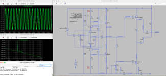
This the "SIT-5" I am working on.

Output stage, follower, where you can set the current through a DC-level converter R15; and the midpoint should be just below half to accomodate the SIT best. Simulation looks not bad.
A small loop maybe Shade feedback will be nice too - Transformer input maybe, but then I have to understand that better.
Top is a plot with the contribution of the two devices. because I have a frame (with F5) that has four pairs of matched K/J devices, three J's can go to the SIT and one set K/J remain in the F5-as-driver.
Next steps.
This DC level shifter works better than a CNY17 opto limiter in my sims. Easier I should say. With an opto coupler the SIT contribution is harder to nail down. I will check the DC current sensitivity. My hunch is that less than 1.9A @ 50V should work too. Something to test in situ.
And a board would be handsome. I am so fed up with my rats nest style, does not allow changes later with lack of precise documentation.
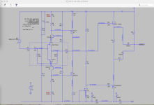
I tested the reduction of the current in the sim of "My SIT-5". The output is constant: 16Vpp out/4Ω
- At 1.5A standing (R15=500), the third harmonics start to rise (-54dB, -58dB) and
- at 1.4A (R=400 the same, and fourth drops);
- at 1.3A (R15=340) the 2nd and 3rd at almost equal.
shall I share the .asc? I know it is what I have at hand now; 2SK180 is still lying around; of course a IXTN40P50P P-MOS 40A. . . puck will work too, but the laterals I have have something special to them.Nice to see values. Allowing to do a Spice
:--))
The DEFISIT is not deficient at all of qualities as follower though. The biasing (with the diodes as voltage droppers) is just different from what I put on the table. I'm just reinventing to balance the ideas deficit.
Last edited:
Yes, .asc would be fine!shall I share the .asc? I know it is what I have at hand now; 2SK180 is still lying around; of course a IXTN40P50P P-MOS 40A. . . puck will work too, but the laterals I have have something special to them.
:--))
Thats a nice integration indeed,
one thing I like to ponder is if there could be the smallest FB from the output even (say 5 to 6-dB) just for the tone of certain speakers that need it - even though the output impedance is 'very low'.
My Maggies yearn for a little spice. Like a dB here or there extra. I have something like that in the preamp where I have a small 1,5dB lift at the bottom , not even a correction but percieved as a phase shift. That gives compliance in the room.
- Home
- Amplifiers
- Pass Labs
- First Watt SIT5