Inspired by lhquam success.....
I tried his way to make the biasing of the output stage, hope I got his decisive idea right.
Because I have no real understanding, it was all done by try and error or copy and paste....
:--))
Helas, I am no lhquam, no ZM and no Nelson of course, so there might be severe faults. You all know LTspice is patient, reality often not.
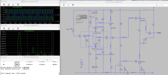
Please comment. How much current do I need to get the 35Watt with 60V rails?
I tried his way to make the biasing of the output stage, hope I got his decisive idea right.
Because I have no real understanding, it was all done by try and error or copy and paste....
:--))
Helas, I am no lhquam, no ZM and no Nelson of course, so there might be severe faults. You all know LTspice is patient, reality often not.
Please comment. How much current do I need to get the 35Watt with 60V rails?
Attachments

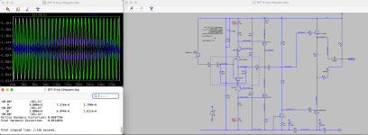
A bit higher current and I adjusted the source resistors at the output to get more contribution of the SIT (green), blue MosFet.
Of course do not take my draft too seriously it is more "entertainment than analysis" to vary a well-known saying....
:--))
Of course do not take my draft too seriously it is more "entertainment than analysis" to vary a well-known saying....
:--))
Attachments
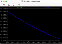
The Rothacher SIT model does not include tempco, so LTSpice cannot tell you much.
However, the resistor from source-to-source doesn't have to be very big for the bias current to be stable.
However, the resistor from source-to-source doesn't have to be very big for the bias current to be stable.
Look at the Rothacher 2SK182ES Spice .SUBCKT model. There are temperature related parameters or computations in that model.
I am afraid I occupy you....
Where is the tempco hidden in the SK180 file?
*2SK180
*GENERATED BY SIT MODELER @ AUDIOHOBBY.COM
*MODEL RANGE: 100V, 2A
*--------------------------------------------------
.SUBCKT 2SK180 D G S ; Drain Gate Source
+ PARAMS: MU=16 X=1.8 K=0.225 N=1.72 VCT=0 RG=2MEG
*--------------------------------------------------
B1 D S I=K*PWR(URAMP((V(G,S)+VCT)+(N*LN(V(D,S))+(V(D,S)/MU))),X)
FOR MULTISIM COMMENT OUT ABOVE LINE () AND UNCOMMENT NEXT LINE
*B1 D S I=K*PWR(MAX((V(G,S)+VCT)+(N*LN(V(D,S))+(V(D,S)/MU)),0),X)
R1 G S {RG}
CGS G S 1500P
CGD G D 0P
CDS G S 0P
.ENDS 2SK180
*--------------------------------------------------
.SUBCKT THF51S 1 2 3 ; Drain Gate Source
+ PARAMS: MU=19.4880 EX=1.204 KG1=0.7031 KP=81.0 KVB=42.0 VCT=2.0 RGI=1MEG
*--------------------------------------------------
E1 7 0 VALUE={V(1,3)/KP*LN(1+EXP(KP*(1/MU+(VCT+V(2,3))/SQRT(KVB+V(1,3)*V(1,3)))))}
RE1 7 0 1G
G1 1 3 VALUE={(PWR(V(7),EX)+PWRS(V(7),EX))/KG1}
RDS 1 3 1G ; TO AVOID FLOATING NODES
D1 5 2 DX ; FOR GRID CURRENT
R1 5 3 {RGI} ; POSITIVE GRID CURRENT
.MODEL DX D(IS=1N RS=1 CJO=10PF TT=1N)
.ENDS
Thank you Ben!
I show them both here: And Lynn is there the tempco visible?
First one:
*--------------------------------------------------
*2SK182ES2
*GENERATED BY SIT MODELER @ AUDIOHOBBY.COM
*MODEL RANGE: 80V, 2A
*--------------------------------------------------
.SUBCKT 2SK182ES D G S ; Drain Gate Source
+ PARAMS: MU=16.98 X=2.56 K=0.443 N=1.6 VCT=0 RG=2MEG
*--------------------------------------------------
B1 D S I=K*PWR(URAMP((V(G,S)+VCT)+(N*LN(V(D,S))+(V(D,S)/MU))),X)
FOR MULTISIM COMMENT OUT ABOVE LINE () AND UNCOMMENT NEXT LINE
*B1 D S I=K*PWR(MAX((V(G,S)+VCT)+(N*LN(V(D,S))+(V(D,S)/MU)),0),X)
R1 G S {RG}
CGS G S 2600P
CGD G D 0P
CDS G S 0P
.ENDS 2SK182ES
*--------------------------------------------------
Second one:
*--------------------------------------------------
*2SK182ES2
*GENERATED BY LHQUAM
*
*--------------------------------------------------
.SUBCKT 2SK182ES2 D G S ; Drain Gate Source
+ PARAMS: MU=16.98 X=2.56 K=0.443 N=1.6 VCT=0 RG=2MEG
*--------------------------------------------------
B1 D S I=K*PWR(URAMP((V(G,S)+VCT)+(N*LN(V(D,S))+(V(D,S)/MU))),X)
FOR MULTISIM COMMENT OUT ABOVE LINE () AND UNCOMMENT NEXT LINE
*B1 D S I=K*PWR(MAX((V(G,S)+VCT)+(N*LN(V(D,S))+(V(D,S)/MU)),0),X)
R1 G S {RG}
CGS G S 17.7nF ; Ciss-Crss
CGD G D 0P ; Crss need a value here
CDS G S 0P ; Coss-Crss
.ENDS 2SK182ES2
*--------------------------------------------------
I found the following on this post: https://www.diyaudio.com/community/threads/the-simplest-defisit-with-2sk182es.373528/post-6693502

As I said several times, the Rothacher SIT model does not include modeling of temperature. It is a functional model described by the equation I=K*PWR(MAX((V(G,S)+VCT)+(N*LN(V(D,S))+(V(D,S)/MU)),0),X), with inter-electrode capacitances added.
Unfortunately, Micheal Rothacher's paper: "A Concise Model for Static Induction Transistor IV Characteristics" is only available by purchasing Linear Audio Vol 6.
Unfortunately, Micheal Rothacher's paper: "A Concise Model for Static Induction Transistor IV Characteristics" is only available by purchasing Linear Audio Vol 6.
I have this article....
it is on Micheal homepage free available.....
:--))
https://passdiy.tv/mrarticles/sitmodel.pdf
it is on Micheal homepage free available.....
:--))
https://passdiy.tv/mrarticles/sitmodel.pdf
In Koren's paper "Finding SPICE tube model parameters" https://www.normankoren.com/Audio/Tube_params.html, there is a description of the VCT parameter:
VCT [0] Contact potential. An offset voltage on the grid that makes curves appear as if they are going positive on a few older tube types (RCA, Sylvania 12AX7, 12AU7).
- Home
- Amplifiers
- Pass Labs
- First Watt SIT5