With this nice explanation from Nelson here
http://www.diyaudio.com/forums/pass-labs/183482-25w-class-amp-lateral-mosfets-14.html
🙂🙂🙂
you can check if your build fulfills the 2dB pos feedback.
In my Spice try I had to choose for the sense resistor a value around 0R6 to get the right pos feedback.
But in my Spice work no ALFS, but SJ162 and SK1058.
The voltage value with an 8 Ohm load has to be 1.26x bigger than the value without the 8 Ohm load.
I don't quite follow the 1.26x value from no load to full load. The closer the 2 values are to each other the higher the damping factor. At 1.26x the damping factor is 3.84,output z is 2 ohms. Nelson's F7 output z is 0.08 ohms for a damping factor of 100. Your pcf resistor is too big.Try your spice models again with lower value resistors till you get close ie. load and no load voltages almost equal.I am using models for exicon equivalents that were generated by St.Andrews( Scotland) engineering dept.
Does anyone have the parameters for the ALFS?
The voltage value with an 8 Ohm load has to be 1.26x bigger than the value without the 8 Ohm load.
Actually, that won't work. If 2 dB is all it takes to make for an inifinite
damping factor, then you will measure exactly the same output voltage with
and without the load.
Where you measure the difference is at the Gate of the input Jfet with and
without load, or you can easily calculate it from the resistive network which is
comprised of the sense resistor and the divider made by the to input resistors.
Aha!
So I misunderstood your comment in the other thread.
Thanks for correcting this, before all try it the wrong way.
I will return to Spice and try to see it in the new way.
And thanks Oreo382 too!
So I misunderstood your comment in the other thread.
Thanks for correcting this, before all try it the wrong way.
I will return to Spice and try to see it in the new way.
And thanks Oreo382 too!
Last edited:

for his 66-th bday , I'm going to send him sch of last iteration of Babelfish XA25
Laugh is great gift , generally

Laugh is great gift , generally
Probably my carelessness.

There is no foolproof information.....😀😀
Iworks!🙂🙂
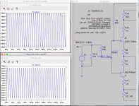
Here you see left upper diagram the input voltage without load, so that PFB is deactivated 50mV
and you see left lower diagram the input voltage with 8 Ohm load, PFB activated.
Ratio 62.3/50 =1.24x = 1.9dB
Thanks Mr. Pass!
Attachments
Exicon are now selling hand selected graded parts.
ECX10N20-S - Selected Lateral Mosfet
ECX10P20-S - Selected Lateral Mosfet
ECX10N20-S - Selected Lateral Mosfet
ECX10P20-S - Selected Lateral Mosfet
I got some today. Doesn't mean they are matched, correct?
It will be fine whatever you have. I was just posting some interesting news.
Trimpots take care of everything.
I was thinking it might possibly be ideal to have jfets of different idss values to compensate for differential current values through each jfet once you start tweaking the source resistance values at the jfet.
Eg Idss value of 8mA and 7mA.
The jfet that has less degeneration use Idss value of 7mA and jfet with more degeneration use Idss value of 8mA.
Doesn't need to be rocket science, a 1mA difference is probably adequate.
Eg Idss value of 8mA and 7mA.
The jfet that has less degeneration use Idss value of 7mA and jfet with more degeneration use Idss value of 8mA.
Doesn't need to be rocket science, a 1mA difference is probably adequate.
Last edited:
I got some today. Doesn't mean they are matched, correct?
Also just to note if you purchase a tube they match extremely well, you don't need hand selected parts for matching. You can see this in my escaped goat thread.
The interesting part about the hand selected parts is not the matching, but you might want parts with higher values for Vgs threshold for a specific circuit (the laterals tend to be low).
Some circuits work better if the Vgs threshold is higher. The variation is not that huge but an extra 0.3V on vgs threshold might be what you need.
Last edited:
Using them to repair a b&k st-140 from 1990. It uses 1058s and 162s. Pairs in parallel.
Absolutely no problem.
I was thinking it might possibly be ideal to have jfets of different idss values to compensate for differential current values through each jfet once you start tweaking the source resistance values at the jfet.
Eg Idss value of 8mA and 7mA.
The jfet that has less degeneration use Idss value of 7mA and jfet with more degeneration use Idss value of 8mA.
Doesn't need to be rocket science, a 1mA difference is probably adequate.
I am using 11ma k170 and 13ma j74.To get the 10 db H2/H3 ratio my K170 degen r is 6 ohms,the J74 degen r is 14 ohms.With matched 8 ma jfets you need 1 ohm on the k170 and 19 ohms on the J74 to get the same result(H2/H3).So unmatched jfets are probably beneficial.
- Home
- Amplifiers
- Pass Labs
- First Watt F7 review