I have done this but sense is after speaker load.
Which lateral mosfets did you use?
Sensing resistor before the speaker is wrong. It has to be connected to ground like in my schematic, is the only way.
Hello mareli. DIYer lhquam has several designs with the sense resistor before the speaker. This gave additional circuits.
Hello mareli. DIYer lhquam has several designs with the sense resistor before the speaker. This gave additional circuits.
Ihquam schematics have positive voltage feedback not real F7.
F7 has current feedback chain.
Hello mareli. DIYer lhquam has several designs with the sense resistor before the speaker. This gave additional circuits.
I don't remember those. Need to go back for a refresh. Thanks for having brought it back to the table
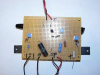
I tried my hand building a "try to duplicate" F7 clone based on Ihquam's type #2. This would not have been possible without the help of a fellow member who filled in the values being that I am only a solder slinger. The sound was fantastic after some listening yesterday.
Attachments
Last edited:
Very nice wdecho! A few nights ago I started putting a type #2 circuit in ltspice.
I hope to build it once I get simulations I like.
Cheers,
Dennis
I hope to build it once I get simulations I like.
Cheers,
Dennis
I am not sure about putting a .1 ohm resister in the positive line. Most power supplies have CRC and can you not set the bias from the middle R on either side. I guess if you have CLC you may have no choice but to me seems wrong even if you do both sides. You could do R(low value)CLC.
What does this mean?
Maybe if the CRC resistors are matched. What happens if they are not? These resistors are 5% tolerance normally.
wouldn't it be better to measure all resistors in CRC and find the value? I don't even think I have a DMM that can read a .47 properly.
Most power supplies have CRC and can you not set the bias from the middle R on either side.
Maybe if the CRC resistors are matched. What happens if they are not? These resistors are 5% tolerance normally.
wouldn't it be better to measure all resistors in CRC and find the value? I don't even think I have a DMM that can read a .47 properly.
Current through parallel resistors
When resistors are connected in parallel, the supply current is equal to the sum of the currents through each resistor. In other words the currents in the branches of a parallel circuit add up to the supply current. When resistors are connected in parallel, they have the same potential difference across them.
Last edited:
I tried my hand building a "try to duplicate" F7 clone based on Ihquam's type #2. This would not have been possible without the help of a fellow member who filled in the values being that I am only a solder slinger. The sound was fantastic after some listening yesterday.
Nice progress. Still tho a perf board assly without heatsinks and only One channel doesn't read as giving reassuring Sound quality judgements.
Not saying that it ain't exquisite.
Just wondering ...How ? can you tell.
OR? is that merely some in process piccie
Papa already did something as that - putting sole 0R1 in rail for Iq measurement purpose (Vfet Amp? ) ............ there is also slight possibility of little influencing THD spectra that way , accent on "little"
however , even if power resistors are 5% or so , setting Iq with same (percentage) accuracy is good enough
however , even if power resistors are 5% or so , setting Iq with same (percentage) accuracy is good enough
What does this mean?
Maybe if the CRC resistors are matched. What happens if they are not? These resistors are 5% tolerance normally.
wouldn't it be better to measure all resistors in CRC and find the value? I don't even think I have a DMM that can read a .47 properly.
If your crc is like the normal one, both boards positives off one side and both board negatives off the other side you can't adjust each board individually very well.Both boards bias adjustments are the sum going thru each r in the crc.This is where the 0.1 ohm in each board positive rail helps. You can adjust each board for bias and offset more accurately
Nice progress. Still tho a perf board assly without heatsinks and only One channel doesn't read as giving reassuring Sound quality judgements.
Not saying that it ain't exquisite.
Just wondering ...How ? can you tell.
OR? is that merely some in process piccie
It was installed on a heatsink before firing up along with the other channel. Picture was taken before being installed on heatsinks. The heatsinks have been installed in wood box with PS section that I call my test chassis. If I cannot live without a build I take the heatsinks from the box and build a proper case and PS section. This may be one of those builds. It is that good.
I have since had reservations about picture and have asked to have it removed since the F7 is a commercial product being sold but as it is not built from an official schematic I did not think Nelson would mind. And since I have not shown the underside I thought it would not hurt posting a picture.
I can say this try at duplication of a F7 sounds mighty fine in the lines of the V-fet but this statement is only from memory. I have not done an A/B comparison as yet. I can say that this build had some of the best square waves between 20 and 20K hz of any of my builds. I am very satisfied with the results. None of this could have been possible without Nelson revealing the concept of improving the F5 with fewer parts using lateral mosfets and employing PCF. I do not believe he will object with a solder slinger giving it a go. I bought ECX10 laterals being that the ALF's are no longer available.
My builds always use separate power supplies for each channel and I had forgotten about using a single supply for both channels. I still think that is the place to measure the bias current.
I never use it. I like to put 0.1 ohms in series somewhere and watch the
voltage drop and that way I never blow the hard to replace fuse on the DMM.
voltage drop and that way I never blow the hard to replace fuse on the DMM.
With this nice explanation from Nelson here
http://www.diyaudio.com/forums/pass-labs/183482-25w-class-amp-lateral-mosfets-14.html
🙂🙂🙂
you can check if your build fulfills the 2dB pos feedback.
In my Spice try I had to choose for the sense resistor a value around 0R6 to get the right pos feedback.
But in my Spice work no ALFS, but SJ162 and SK1058.
The voltage value with an 8 Ohm load has to be 1.26x bigger than the value without the 8 Ohm load.
Does anyone have the parameters for the ALFS?
- Home
- Amplifiers
- Pass Labs
- First Watt F7 review