Thank you for all that! I always very much appreciate the long/in-depth explanations!
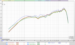
I have taken the FF FR of all the tweeters, the picture is below. They are looking good and consistent. Also, keep in mind these responses have not taken into account the baffle diffraction, I will explain why below.
So, Response Blender is not letting me import any FRD files.
(Yeah thats my bad about .imp from before haha I was thinking it was impulse response. But yeah it is impedance)
I enabled all macros and have looked up what other people did with the same problem, but found no luck.
What I'm thinking is I can get the baffle diffraction FRD file from Diffraction & Boundary Simulator and then use REW to add the two. Thoughts? Also, that spreadsheet has the Diffraction Modeled as either a Gain or Loss. Just checking, but to my knowledge I need the file to be modeled as a Loss.
To my knowledge, the Response Blender can do everything that REW can. So, I can stick with REW and use the Diffraction & Boundary Simulator spreadsheet. Idk yet, but I'm still trying to see what I can do with Response Blender to get it to work correctly.
Update:
I will actually try the Response Blender on my windows side and see if that fixes it.
Attachments
Last edited:
That's great with the tweeters. There looks to be a reasonable amount of consistency. Here's what I'm thinking about them. Re-measure the impedance and let's see if there is more consistency there too than the 1st time. If there isn't, let's try to match them up into similar pairs for the paired speakers and leave the outlier for the CC before doing any more measurements.
Did I mention that certain Excel programs can be finicky in different versions of Office? That could be the problem with Response Blender but there are often 3 other things that can go wrong in terms of file loading.
First is that the file extension is incorrect. This is especially easy to occur with files from REW because it will save them as .txt files unless you specify otherwise. If that's the case, just simply rename them with .frd as the file extension.
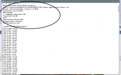
Secondly, some programs don't like the info that can be inserted in the frd file before the actual numbers. Open up the frd file (just double click on it and it will open as a Notepad document) and then just delete the text and/or empty lines. See pic 1 circled.
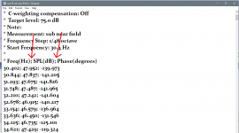
Lastly, again in the actual text of the frd file, in each line the 3 points of data can be separated by different means. Very typically, it's just done with an empty space or a tab but REW likes to put semi-colons in between them (pic 2). Open up your frd files just to make sure and then when you load them into Response Blender, check the little box called 'Show Import Options', click "Import FRD File' and in the window that pops up, select 'User Defined' and type in ";" (or make one of the other choices if that's appropriate). This is what I think the problem is most likely to be.
I can also tell that you don't quite have a grasp on what Response Modeler is doing and that's ok. Lost and lots of info that you've been absorbing lately. In terms of the order of things maybe it doesn't matter much, but this is the reason that I want to just get you to measure the simplest speakers to start off with (the surrounds) and then run the data through the AC analysis and then the response blending process. That'll give you a better idea of what's going on and the difference between REW and Response Blender for eg. And I hope it's a more manageable way of learning too.
Did I mention that certain Excel programs can be finicky in different versions of Office? That could be the problem with Response Blender but there are often 3 other things that can go wrong in terms of file loading.
First is that the file extension is incorrect. This is especially easy to occur with files from REW because it will save them as .txt files unless you specify otherwise. If that's the case, just simply rename them with .frd as the file extension.
Secondly, some programs don't like the info that can be inserted in the frd file before the actual numbers. Open up the frd file (just double click on it and it will open as a Notepad document) and then just delete the text and/or empty lines. See pic 1 circled.
Lastly, again in the actual text of the frd file, in each line the 3 points of data can be separated by different means. Very typically, it's just done with an empty space or a tab but REW likes to put semi-colons in between them (pic 2). Open up your frd files just to make sure and then when you load them into Response Blender, check the little box called 'Show Import Options', click "Import FRD File' and in the window that pops up, select 'User Defined' and type in ";" (or make one of the other choices if that's appropriate). This is what I think the problem is most likely to be.
I can also tell that you don't quite have a grasp on what Response Modeler is doing and that's ok. Lost and lots of info that you've been absorbing lately. In terms of the order of things maybe it doesn't matter much, but this is the reason that I want to just get you to measure the simplest speakers to start off with (the surrounds) and then run the data through the AC analysis and then the response blending process. That'll give you a better idea of what's going on and the difference between REW and Response Blender for eg. And I hope it's a more manageable way of learning too.
Attachments
Yeah using Response Blender on windows made it work which is good. I was unable to import still, but that suggestion you made makes so much sense.
I've got the measurements for one of the surrounds and making sure that the outcome is correct with the softwares.
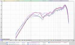
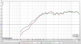
The picture below is a look at all the tweeters with the baffle diffraction files from Diffraction & Boundary Simulator and did the A*B summation in REW. Just to get a look at it. I will be using Response Blender now and see how it goes!
I've got the measurements for one of the surrounds and making sure that the outcome is correct with the softwares.
The picture below is a look at all the tweeters with the baffle diffraction files from Diffraction & Boundary Simulator and did the A*B summation in REW. Just to get a look at it. I will be using Response Blender now and see how it goes!
Attachments
Ok, Response Blender is used to blend the FF and the NF measurements but with the tweeters, all you need is the FF. So no need to use Response blender for them. Although I guess you could if you wanted to for practice.
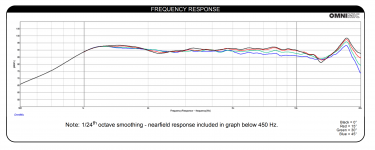
On another note, it took me until after I posted to stop and realize that although those tweeters are showing some consistency, the FR's do not look right at all. They don't actually look anything like the spec sheet nor the spec sheet FR combined with any of the baffle responses. Attached are the spec FR and the sim for the surround.
So I'm starting to worry there is something off about the measurements or the tweeters.
Attachments
Oh ok. Have you added in the simmed baffle diffraction response to the measurement that already contains the baffle diffraction response??
Hmmm, that is odd. Honestly these tweeters are a pain in the a-s-s.
Maybe again Dayton did not have accurate results, which I doubt. Yet, all my other impedance results looked good except the tweeters, then now the FR is odd too.
Idk where I could have gone wrong, I've been following all the steps and taking this all into account. Like I said I even put up foam and sheets and more rugs down, probably more than I need, to help with reflections.
But ya know, I'll try breaking them in like you have said. See what that does for it.
To answer your question, that actually makes sense. Okay, so if I measured the FR of the tweeters while they are in the speakers, that means that the baffle diffraction is already in the response, so I dont need to add it in again? Or, when I take the FR of the drivers, I need to add in the simmed baffle diffraction loss in order to get a more true final response?
Also, importing the FRD files from REW, making sure they are saved as .frd files with semi-colons. Then I deleted the text and empty lines. Then in Response Blender I did the User Defined as ;
That still did not work unfortunately.
Last edited:
So let's deal with 1 thing at a time.
When doing FF measurements, the point is to get the mic far enough away so that baffle effects are included, but not too far away and not for too long of a gating time so that the room effects are included.
The near field on the other hand only includes the driver response without any baffle or room effects. Thus when putting the FF and the NF measurements together for a woofer or mid (not the tweeters because the whole FR is included in the FF measurement), we need to add in the diffraction response to the NF measurement but not the FF measurement.
So I'm hoping that the tweeter FR's you posted include the baffle diffraction twice which would account for the serious ski hill going down to the left of the frequency range. If that's so, let's try again and post just the unadulterated FF measurements for the tweeters.
Maybe just attach the whole REW tweeter measurement session if that's easier. I think you'll have to zip it first though.
So, the first screencapture I posted of the tweeters FR's is just the raw measurements with nothing added to them.
The REW file for all the tweeter measurements is too large to post, I will email it. The file has nothing done to them besides 1/48th octave smoothing and gating at 3ms.
The REW file for all the tweeter measurements is too large to post, I will email it. The file has nothing done to them besides 1/48th octave smoothing and gating at 3ms.
Last edited:
Got your email but I can't open it, I think because I have an older version of REW installed and I haven't felt like installing a new version because I didn't feel like going through the setup all over again. But maybe I will anyways....
But I was afraid you were going to tell me that the measurements of the tweeters you attached in post #161 were correct. Yea, because those are just not right. It's as if there is a 10dB treble boost starting at ~ 3-4kHz. Do either of the 'AIR' or 'INST' settings on the Focusrite by any chance operate like an EQ setting?
But I was afraid you were going to tell me that the measurements of the tweeters you attached in post #161 were correct. Yea, because those are just not right. It's as if there is a 10dB treble boost starting at ~ 3-4kHz. Do either of the 'AIR' or 'INST' settings on the Focusrite by any chance operate like an EQ setting?
Oh dang sorry about that. I found downloading the new version of REW quite easy to be honest. It is up to you! I can send the download files if you'd like or something to do to help just lemme know!
Yeah that picture from post #161 were correct. Idk what this looks like to me is a high frequency resonance from the metal dome. I remember when I did my speaker project for school I used the Dayton Audio ND25TA-4 1" Titanium Dome Neodymium Tweeter. In the FR of that it has something kinda similar where it peaks up toward 15kHz. The professor and I's thought was that it was due to the metal dome over it.
I know these measurements I made are different, but yeah it is odd how it ramps up like that. Maybe I should email Dayton about it like you had before.
The input switches I believe do not act as an EQ setting, only for either Line Level of Instrument level stuff. I do not know what 'AIR' is, I dont have anything like that on the interface.
I also forgot to add the mic calibration file to the tests yesterday, the file was on the wrong input. Yet I did some tests and it didnt change anything very much to be honest.
Also, I tried testing at higher sample rates and I got different results which was very odd. Just like a different response on the low end and a lot more peaks and valleys in places that didnt match with the regular sample rate I was using of 48kHz.
Also, did the sound card calibration and after that the tests all came back like really flat and the low end was all weird. It looked just like an impulse response. So, idk if I did that wrong or what, I followed all the steps right. Also dont know if that is necessary either.
Last edited:
I got Response Blender to import the files now! I used spaces in between the data values and also clicked "Use CRLF as end of line for Window compatibility" and that worked! So I've been messing with that and its all working on that end which is good!
I'm afraid to go through all the testing right now due to the tweeters being weird. Like, I dont want to do it all to then realize it was all wrong ya know.
Yet, yeah I feel like this big road that we need to cross is ensuring these FR tests I'm doing is accurate. Which is most important.
I'm afraid to go through all the testing right now due to the tweeters being weird. Like, I dont want to do it all to then realize it was all wrong ya know.
Yet, yeah I feel like this big road that we need to cross is ensuring these FR tests I'm doing is accurate. Which is most important.
I expect downloading is easy. It's going through it and setting it up again that takes a little time. Last time I did it was more than a couple of years ago. But maybe that's on the agenda for this evening.
Regardless of the cone/dome material, any driver should measure at least somewhat similar to the spec sheet, resonances included which should show up in the waterfall plot hopefully.
I was looking at the Focusrite below. Guess that's not the one you have. lol
No difference with the mic calibration file? Guess that means your mic is pretty accurate.
I just tried a higher sample rate and there was no difference. Mine is normally set at 48kHz.
I needed to do a soundcard calibration when I used a desktop computer but with a laptop without an external soundcard, I'm not able to do one. FR measurements still work out fine with a USB mic. But I still use my older desktop for the impedance measurements.
If there is some kind of eq problem, it should show up in all the driver tests. So maybe try one last attempt and measure your surrounds. First the tweeter and then the woofer. No changes etc. etc. Don't even worry about gating. Mic distance somewhere around 20".
I think if the tweeter still looks bad but the woofer looks ok, we can conclude that there is something wrong with the tweeters. Unless we're missing something else that I can't think of, obvious or otherwise.
Attachments
Good to hear about Response Blender.
You know if you had any other tweeters laying around, I would tell you to measure those too and see what you get. Or even a tweeter in an existing speaker if you could separate the input to just the tweeter.
Too bad no one else seems to be following along on the thread. Some other input might come in handy right about now.
Oh yeah I have the 2nd gen of the 2i2 haha.
I am able to actually add the mic calibration file after the fact to the measurements which is nice. Just a very small difference, but nothing huge at all.
Yeah actually I have my old speaker build from school and the crossover and everything is just taped to the top. So I can easily disconnect the tweeter and test it. I will for sure do that, thank you for the tip.
I was also just messing around with the Passive Crossover Designer from Jeff, and I was unable to import any files correctly. It would import fine up to like 80Hz and then flatten out. Idk, not a big problem. Idk if we will be using that.
Ok, do a little more measuring and let's see if that helps.
PCD is a good program with advantages and disadvantages. Although Jeff's paper about relative acoustic centers uses PCD, you can also use XSim.
Something else you can try to determine problems with loading is to try to load other files. Go to Parts Express and you'll find that Dayton drivers have the frd and zma files included for download. You might try any of those and see if they work when you load them into different programs. Then open the different frd files themselves and see if and/or what the differences in formatting are that work and don't work. But yea, Excel isn't really too friendly any more these days.
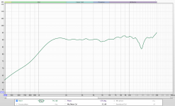
Wow yeah, the tweeter from my old build looks way more accurate to the spec sheet then the tweeter now for this build.
The first picture is of my measured response with the mic 8in away. Then the second is from the spec sheet.
So haha wow idk whats up with these new tweeters now. Maybe they really are just off form the spec sheet or somehow defective.
The first picture is of my measured response with the mic 8in away. Then the second is from the spec sheet.
So haha wow idk whats up with these new tweeters now. Maybe they really are just off form the spec sheet or somehow defective.
Attachments
- Home
- Loudspeakers
- Multi-Way
- First-Timer Home Theater Speaker Build