Actually that is the trick, when REW says inputs of L and R that means 1 on the Focusrite is L and 2 is R!
I've been trying to do L and R from one channel.
I've been trying to do L and R from one channel.
Sorry, it's not quite clear to me if you've got it working? But I agree REW's instructions could be better.
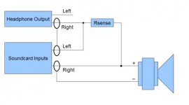
Let's go over things. Your headphone output should consist of 3 wires - L, R and ground and therefore needs a stereo jack which is separated into 3 segments. If your Focusrite input 1 and 2 correspond to the L and R inputs then they will each only have 2 wires, positive and ground although I'm confused on that because it looks like the Focusrite inputs are stereo 3 pin XLR connectors.
To do the impedance measurements and/or the impedance calibration, you have to use the impedance jig (pic 1) which only uses the Right side of the headphone output. The Left channel remains unused. And importantly, the Right channel gets split and sent to both the L and R input channels. If you just use a normal cable from the output to the inputs, this isn't going to work properly.
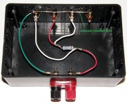
So first, grab whatever is necessary and make yourself up a nice little box that has the correct wiring and that you can repeatedly plug your input and output connectors in and out of and attach the 2 leads for a driver connection too. Pics 2 and 3 are a good example of the wiring but the connectors you use are going to be dependent on your Focusrite I guess - maybe a 1/4" stereo female for the headphone input and then any 2 female connectors that you want to put together on the jig end and then XLR connectors on the other. That wiring is going to be dependent on if the Focusrite inputs are single channel or stereo.
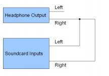
Now for the jig calibration, bypass the resistor and don't connect a driver to it and then run the test. That means that the right channel only from the headphones will be running directly into the L and R channels of the inputs, that's in pic 4. Notice that the ground wiring has unhelpfully been left out of this diagram, as well as the resistor and the driver connections.
Does that help?
Let's go over things. Your headphone output should consist of 3 wires - L, R and ground and therefore needs a stereo jack which is separated into 3 segments. If your Focusrite input 1 and 2 correspond to the L and R inputs then they will each only have 2 wires, positive and ground although I'm confused on that because it looks like the Focusrite inputs are stereo 3 pin XLR connectors.
To do the impedance measurements and/or the impedance calibration, you have to use the impedance jig (pic 1) which only uses the Right side of the headphone output. The Left channel remains unused. And importantly, the Right channel gets split and sent to both the L and R input channels. If you just use a normal cable from the output to the inputs, this isn't going to work properly.
So first, grab whatever is necessary and make yourself up a nice little box that has the correct wiring and that you can repeatedly plug your input and output connectors in and out of and attach the 2 leads for a driver connection too. Pics 2 and 3 are a good example of the wiring but the connectors you use are going to be dependent on your Focusrite I guess - maybe a 1/4" stereo female for the headphone input and then any 2 female connectors that you want to put together on the jig end and then XLR connectors on the other. That wiring is going to be dependent on if the Focusrite inputs are single channel or stereo.
Now for the jig calibration, bypass the resistor and don't connect a driver to it and then run the test. That means that the right channel only from the headphones will be running directly into the L and R channels of the inputs, that's in pic 4. Notice that the ground wiring has unhelpfully been left out of this diagram, as well as the resistor and the driver connections.
Does that help?
Attachments

My bad that was unclear, should have said for sure to save you from an explanation. But, yes I got it to work!
The Focusrite has their channel to be either XLR or a 1/4" jack. There are the little switches that are form either Line or Inst. I think when you plug in a mic though it automatically reads the three pins. But yeah I have two 1/4" jacks wired to speaker wire that I used for a project a few years back, so that works out very nice!
I dont have a sturdy box to make one of those now and also no screw terminals on hand.
Though I do have a little rig on my workbench now for easy testing.
I got it all working at the end of the day, so I will be finishing up the impedance testing today and sending some screenshots.
Thank you for letting me know about this because even though it was a pain yesterday, this process makes it all much faster and easier haha.
Excellent. The 1 day of pain is definitely worth it.
So it's up to you how you want to proceed. You can run through all the speakers and take each set of measurements all at once. Or we can look at just the simplest speaker, the surrounds, and just work with that one to start with, check everything out and perhaps iron out any bugs before proceeding to the rest.
For impedance, I still might suggest starting with a resistor between the load connections instead of a driver just to test the accuracy of the setup before proceeding with a slew of measurements.
Okay sounds good. Actually went through the surrounds and CC testing already.
But yeah lemme test with a resistor at the load first, thats a good idea.
But yeah lemme test with a resistor at the load first, thats a good idea.
My REW just got very slow and will not show the graphs anymore, as if it's not responding. So I cannot screenshot the results right now.
But I found a newer download of REW online but had to register to the forum for the download, so I gotta wait on that.
Also, some things have come up and I wont be able to send a detailed response today anyways. But, right before REW stopped I was able to test the jig with a 10 ohm resistor and REW was very accurate on the readings. Which is very nice to know!
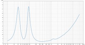
Alright so here are screen captures of the tests I have already done.
In order:
(1) CC Left Woofer AVG
(2) CC Right Woofer AVG
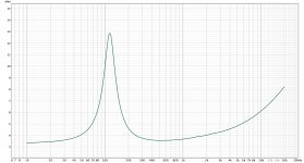
(3) CC Mids Parallel AVG
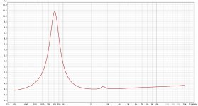
(4) CC Tweeter AVG
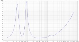
(5) Rear (B) Woofer AVG
(6) Rear (A) Woofer AVG
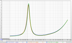
(7) Rear (A)(B) Woofer AVG Comparison
(8) CC Right-Left Woofer AVG Comparison
So, for all the graphs you see (except the tweeter) I did 5 tests back to back and then took the average to get a larger sample size on the results. For the tweeter I did 10 samples then took the average.
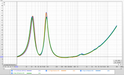
For the Rears Woofer comparison capture:
-> Rear (A) = green
-> Rear (B) = blue
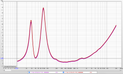
For the CC Woofer comparison capture:
-> Right Woofer = brown
-> Left Woofer = teal
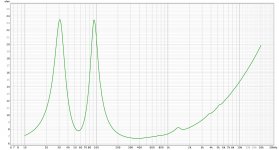
I will be doing the towers here soon. But so far everything is looking good to me. I am getting consistent readings of within ~0.5 ohms difference at the peaks for the Rears. For the CC woofers, on the rise from 10Hz till 33Hz there is a slight difference in the consistency, yet I feel that slight difference is negligible and would be unable to be heard at all.
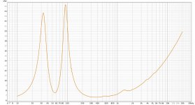
Now, for the tweeter the impedance readings look similar but have some discrepancies. For one, the resonance frequency from the spec sheet (attached below) is 710Hz @ 8.2 ohms and my readings show me 810Hz @ 10.4 ohms.
So, that is pretty off. Yet, the shape looks the exact same for both the spec sheet and my results. They both also have a little hump in between 2kHz-3kHz.
Yet, the spec sheets has it at 2.4kHz and my readings are at 2.7kHz.
While testing the tweeter, I did not screw the speaker wire terminal back one since the tweeter does not rely on the inside of the box. I do not think that would change my results, but I will be testing the Rears tweeters right now and see if I get consistent results to to CC tweeter.
I will be testing the rest now and hopefully have time to upload them.
So yeah, cheers Chris! Thanks as always for the huge help you are! Never had I thought that someone from the internet would want to consistently help a poor speaker building soul as myself But you have showed me otherwise!
With quarantine my options were limited, so joining a forum was my last resort after professors stopped responding to me. But, wow am I glad to be on this forum! I have learned a ton.
In order:
(1) CC Left Woofer AVG
(2) CC Right Woofer AVG
(3) CC Mids Parallel AVG
(4) CC Tweeter AVG
(5) Rear (B) Woofer AVG
(6) Rear (A) Woofer AVG
(7) Rear (A)(B) Woofer AVG Comparison
(8) CC Right-Left Woofer AVG Comparison
So, for all the graphs you see (except the tweeter) I did 5 tests back to back and then took the average to get a larger sample size on the results. For the tweeter I did 10 samples then took the average.
For the Rears Woofer comparison capture:
-> Rear (A) = green
-> Rear (B) = blue
For the CC Woofer comparison capture:
-> Right Woofer = brown
-> Left Woofer = teal
I will be doing the towers here soon. But so far everything is looking good to me. I am getting consistent readings of within ~0.5 ohms difference at the peaks for the Rears. For the CC woofers, on the rise from 10Hz till 33Hz there is a slight difference in the consistency, yet I feel that slight difference is negligible and would be unable to be heard at all.
Now, for the tweeter the impedance readings look similar but have some discrepancies. For one, the resonance frequency from the spec sheet (attached below) is 710Hz @ 8.2 ohms and my readings show me 810Hz @ 10.4 ohms.
So, that is pretty off. Yet, the shape looks the exact same for both the spec sheet and my results. They both also have a little hump in between 2kHz-3kHz.
Yet, the spec sheets has it at 2.4kHz and my readings are at 2.7kHz.
While testing the tweeter, I did not screw the speaker wire terminal back one since the tweeter does not rely on the inside of the box. I do not think that would change my results, but I will be testing the Rears tweeters right now and see if I get consistent results to to CC tweeter.
I will be testing the rest now and hopefully have time to upload them.
So yeah, cheers Chris! Thanks as always for the huge help you are! Never had I thought that someone from the internet would want to consistently help a poor speaker building soul as myself
But you have showed me otherwise! With quarantine my options were limited, so joining a forum was my last resort after professors stopped responding to me. But, wow am I glad to be on this forum! I have learned a ton.
Attachments
-
 Rear (A) Woofer AVG.jpg262.9 KB · Views: 54
 -
 Rear (B) Woofer AVG.jpg263.2 KB · Views: 62
 -
 CC Tweeter IMP.jpg243.9 KB · Views: 55
 -
 CC Mids Parallel AVG.jpg238.2 KB · Views: 63
 -
 CC Right Woofer AVG.jpg261 KB · Views: 57
 -
 CC Left Woofer AVG.jpg261.9 KB · Views: 126
 -
 Rear (A)(B) Wooofer AVG Comparison .jpg263.3 KB · Views: 53
 -
 CC Right-Left Woofer AVG Comparison.jpg276.6 KB · Views: 57
 -
dayton-audio-rst28f-4-specification-sheet.pdf229.7 KB · Views: 71
Much better this time. I think all of those are good enough to work with.
Very often driver resonances may be just a little higher than what the spec sheets say. But often they will also drop down some after they are broken in. In either case, it's not enough for me to worry about. Let's see what the other ones look like too.
Completing all the impedance measurements next looks fine now. For the FR measurements, just start with the surrounds just to make sure everything is working out well first. Take a measure of the port nearfield too. We don't really need it to add it into the nearfield woofer measurement as described in the measuring paper (unless you want to try it), but it can give us some insight into whether or not there are any unwanted resonances coming through the port as well.
Happy to be of help btw. For various reasons my building days are mostly behind me so I'm living somewhat vicariously here. Plus, I always end up learning a little more every time I try to teach this stuff. And especially during this past year, feeling useful is always helpful to the psyche.
Alright so I got all of them done. For the most part everything is looking good and consistent, except for the tweeters. Which is very odd.
Here are the captures in order:
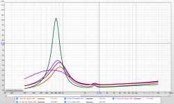
- Tweeters from all 5 boxes
- The Mids in Parallel from the CC and Towers
- The woofers in parallel from the towers
- The woofer individually from the CC and Rears
The thing that is really sticking out to me are the tweeter differences. They are all just so off. The Rears and Tower (A) all have kind of similar results, yet still off. Then Tower (B) and the CC are so different from the rest.
I made sure all connections were really good and tight, also tested each one 10 times and took the average. Each time I tested it always looked the same, there were no outliers. I even went back and tested the CC and Tower (B) a second time, ending up with the same exact results.
I haven't broken in any of the tweeters, all the same. I have also been very careful when building and fitting the tweeters on the boxes that no dust gets on them, and if so just a tad that was blown off. I had let one of the tweeters stay in the garage for a couple days in the box of course, but I was running heaters and it wasn't crazy cold in there.
Wondering whats goin' on with these crazy findings, any clue?
So, as far as the rest, it looks pretty consistent which is nice.
- The mids in parallel look very true to the spec sheet which is good.
- The woofers in the towers still have a tuning frequency around 40Hz. Should I address that before moving on to the FR tests?
- The woofers in the rears and CC seem fairly consistent, yet I do not know what to look for there.
Here are the captures in order:
- Tweeters from all 5 boxes
- The Mids in Parallel from the CC and Towers
- The woofers in parallel from the towers
- The woofer individually from the CC and Rears
The thing that is really sticking out to me are the tweeter differences. They are all just so off. The Rears and Tower (A) all have kind of similar results, yet still off. Then Tower (B) and the CC are so different from the rest.
I made sure all connections were really good and tight, also tested each one 10 times and took the average. Each time I tested it always looked the same, there were no outliers. I even went back and tested the CC and Tower (B) a second time, ending up with the same exact results.
I haven't broken in any of the tweeters, all the same. I have also been very careful when building and fitting the tweeters on the boxes that no dust gets on them, and if so just a tad that was blown off. I had let one of the tweeters stay in the garage for a couple days in the box of course, but I was running heaters and it wasn't crazy cold in there.
Wondering whats goin' on with these crazy findings, any clue?
So, as far as the rest, it looks pretty consistent which is nice.
- The mids in parallel look very true to the spec sheet which is good.
- The woofers in the towers still have a tuning frequency around 40Hz. Should I address that before moving on to the FR tests?
- The woofers in the rears and CC seem fairly consistent, yet I do not know what to look for there.
Attachments
Last edited:
Also about the FR tests, since I will start to do that now and mess around with it.
In accordance to the "How to Achieve Accurate In-RoomQuasi-Anechoic Free-Field Frequency Response Measurements Down to 10 Hz" by Jeff Bagby, I need to do both Far-Field and Near-Field measurements. Then, I essentially use his Excel spreadsheet and merge the two with the tips in that paper.
So, my question is about the mic being at the height of the tweeter again.
If I am measuring the FR of the lower woofer and I need both far and near responses, yet the near-field response needs to be very close to the driver and at the center of the cone. So, wouldn't the far-field measurement need to also be directed at the center of the woofer cone too in order to not have the far-field part of the merged result have phase differences from the near-field?
Those are just my thoughts on it, I could be very wrong and the paper said nothing about the direction of the mic for the far-field.
Correction:
The paper did say in the example portion that he took the far-field measurement on axis with the woofer. So, for what measurements should I have the mic at the tweeter level. I'm guessing for when I do the driver pair testing.
Last edited:
I'm just going to spill what I did today with the FR measurements and wondering if it aligns with what you would expect and do with REW as well:
FYI, I used the methods from the white paper by Jeff Bagby for the far-field, near-field, port consideration, and octave smoothing. I took into consideration, yet did not follow the exact methods for the gate and measurement blending, due to how REW is set up differently.
I also used 1/48th octave smoothing for all traces.
Procedure I used: For the top woofer on Tower (A)
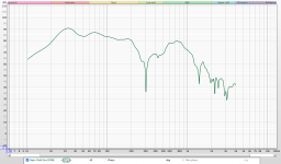
1) I did a far-field test with the mic 14" away from the center of the cone. Then set the IR Windows to:
- Left Window (ms) = 5
- Window Ref Time (ms) = auto set
- Right Window (ms) = 5
Picture 1
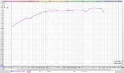
2) Took a near-field test with the mic 0.225" away from the center of the cone. Then set the IR window to:
- Left Window (ms) = 100
- Window Ref Time (ms) = auto set
- Right Window (ms) = 100
Picture 2
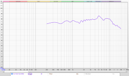
3) Took the near-field test with the mic basically right inside the curve of the port. Then set the IR window to:
- Left Window (ms) = 10
- Window Ref Time (ms) = auto set
- Right Window (ms) = 100
I also, lowered the port SPL by, the equation given in the white paper, -3.522dB
Picture 3
4) Then I took the average of both near-field measurements for a total near-field FR.
Picture 4
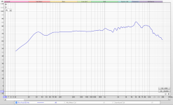
5) I then looked at both the FF and NF responses and lowered the NF by -14.8dB to line them up.
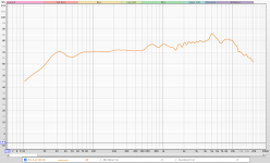
6) I then used the 'Trace arithmetic' feature on REW to 'Merge' the two responses at 500Hz with blending. I also tried blending at 850Hz and that looked good too.
Picture 5 - @500Hz
Picture 6 - @850Hz
I did these tests in my room to just figure out the process more. But, when I have the procedure nailed down and right. I will most likely be moving to the basement where the walls are much farther away.
FYI, I used the methods from the white paper by Jeff Bagby for the far-field, near-field, port consideration, and octave smoothing. I took into consideration, yet did not follow the exact methods for the gate and measurement blending, due to how REW is set up differently.
I also used 1/48th octave smoothing for all traces.
Procedure I used: For the top woofer on Tower (A)
1) I did a far-field test with the mic 14" away from the center of the cone. Then set the IR Windows to:
- Left Window (ms) = 5
- Window Ref Time (ms) = auto set
- Right Window (ms) = 5
Picture 1
2) Took a near-field test with the mic 0.225" away from the center of the cone. Then set the IR window to:
- Left Window (ms) = 100
- Window Ref Time (ms) = auto set
- Right Window (ms) = 100
Picture 2
3) Took the near-field test with the mic basically right inside the curve of the port. Then set the IR window to:
- Left Window (ms) = 10
- Window Ref Time (ms) = auto set
- Right Window (ms) = 100
I also, lowered the port SPL by, the equation given in the white paper, -3.522dB
Picture 3
4) Then I took the average of both near-field measurements for a total near-field FR.
Picture 4
5) I then looked at both the FF and NF responses and lowered the NF by -14.8dB to line them up.
6) I then used the 'Trace arithmetic' feature on REW to 'Merge' the two responses at 500Hz with blending. I also tried blending at 850Hz and that looked good too.
Picture 5 - @500Hz
Picture 6 - @850Hz
I did these tests in my room to just figure out the process more. But, when I have the procedure nailed down and right. I will most likely be moving to the basement where the walls are much farther away.
Attachments
-
 Screen Shot 2021-02-05 at 4.45.24 PM.png371.5 KB · Views: 54
 -
 Screen Shot 2021-02-05 at 4.45.12 PM.png362.3 KB · Views: 119
 -
 Screen Shot 2021-02-05 at 4.44.52 PM.png328.3 KB · Views: 117
 -
 Screen Shot 2021-02-05 at 4.44.42 PM.png361.1 KB · Views: 121
 -
 Screen Shot 2021-02-05 at 4.44.31 PM.png319.8 KB · Views: 123
 -
 Screen Shot 2021-02-05 at 4.44.15 PM.png327 KB · Views: 133
I'm short on time this evening so just quickly:
- Not really sure what's going on with the tweeters. The others look good. Maybe imp will change if the tweeters get worked in a bit but I'm not hopeful. Let's see what the FR's look like too first.
- For all the farfield FR measurements: the mic should always stay stationary on the listening axis (usually the tweeter height) for each speaker's farfield measurements. You want the same power to each driver and the same mic position so that all drivers' relative SPL levels are correct. If the tweeter is the listening axis, then all other drivers with the exception of the CC will be listened to off-axis so this is how we want to measure them too.
- For nearfield, then you move the mic for each driver or port that you measure and then we'll adjust those levels to match correctly with the farfield measurements. I haven't actually measured drivers with phase plugs before so I'm not sure which instruction should prevail - proximity to the cone or in the center of the cone. I'm inclined to say the center of the cone, so right in front of the phase plug and then maybe go with a little higher SPL.
- When blending, you have to add in the baffle diffraction to the nearfield measurement before you can blend it correctly with farfield.
- Try to ensure all drivers are 3' to 4' from all surfaces including floor and ceiling. That may mean raising the towers up a bit too. Choice of the gating time will be dependent on how far the nearest surface is. This can be spotted in the impulse response and/or it can be double checked with some simple geometry and the equation for speed=distance/time.
I'll try for more detail tomorrow.
Thats right I forgot to blend in the baffle diffraction to the near field.
But that all sounds good, I will begin testing Monday then!
But that all sounds good, I will begin testing Monday then!
So just repeating from last night, I agree that the measuring paper misses a couple of key points. The first is that the mic should stay fixed on the listening axis for all FF measurements and the 2nd is what to do for NF when the driver has a phase plug.
Re your FR measurements:
1. First it looks like there is too much smoothing. It looks more like 1/6 or 1/12 than 1/48 smoothing to me. If you didn’t just pick the wrong one in the drop-down ‘Graph’ window, go to Preferences -> Analysis - > Frequency Response Calculation and make sure that 1/48th is selected.
2. Woofer FF: Comparing your measured FR to my sim with baffle effects included, it looks about right. I’d probably use a gating window of 3ms though. Check your impulse response to look for any blips under that amount of time. Or looking at time of flight, 5ms will record any sound source, direct or reflected, with a pathlength less than about 67”, which means you’ll need clearance of about 5ft to all surfaces near the woofer. I’m guessing but I think the floor was probably only about 20” away from the driver. Three ms on the other hand only allows a direct or indirect sound source to be recorded within 40”. *
The accuracy of a 3ms measurement btw will go down to about 333Hz.
3. Woofer NF: Not sure how much difference it would make but 50ms will be accurate down to 20Hz. I’d go for that instead of 100ms.
Just fyi: Driver piston diameter is generally considered to be the distance peak to peak on the surround. More or less.
I would expect to see a deeper null at the tuning frequency, so around 40Hz but I think this is just an artifact of over smoothing.
4. Again, not 100% sure but I typically set the L and R gating to the same amount.
With the port, it looks like there is more SPL at ~70Hz and ~800Hz than wanted. The 800Hz doesn’t matter at all because that frequency will be out of the passband of the woofer. Not sure about 70Hz. Let’s see if shorter gating changes things. Or maybe we need the NF source, the port, to be louder than the cone source so maybe turn it up a little bit more. The drivers should be able to handle it!
5. Averaging the woofer NF and the port NF responses may work as a combining method but I’m doubtful. Jeff’s paper suggests using a xo sim program that uses SPL levels plus phase info to add them together but I don’t find it necessary to add them together usually in the first place because for xo work, the reference SPL of the woofer’s FR that sets the speaker’s overall level is at about 200Hz, which here should be well above the contribution from a port tuned to about 40Hz.
*If you wanted to calculate the path length for reflected sound waves, it’s a pretty straight forward formula.
If h2 = the distance of the mic from a surface, and h1 = the distance from the center of the driver to the same surface, and d = the horizontal distance from the cabinet to the mic, the distance of the reflected path length, L is:
L = sqrt[(h2-h1)^2 + d^2]
(Obviously if h1 > h2, then it’ll be (h1 – h2).)
Good work on the measurements so far btw. I figured that with someone with your background, you'd be able to pick up this aspect of the process pretty quickly.
So next up I would probably look at the FR of all the tweeters. I think you need to know if those tweeters are going to be ok or not before going too much further. Maybe give them a little workout before hand to make sure they are well worked in.
For the tweeters by themselves, FF only is fine and the mic can get closer than with the woofers.
Also when you get the time, can you post your final diagrams of the speaker cabinets. I'm not sure that I have the final versions for all of them and this info might possibly help me in the analysis of any of the measurements.
All sounds good thank you very much!
I am preparing the basement for testing with making an open space for the speakers and mic. Also putting up foam mattresses and blankets where I can to at least help a little with possible reflections. Even though all walls are around 7 or more feet away.
Also, the smoothing was actually 1/48th or 1/24th octave for those, I was kinda messing around. But, I will make sure all are just 1/48th octave smoothing when I test.
For when I test tomorrow I have a few questions.
1) So I understand the gated time and where that should be. But I am still confused about the 'Left Window' part, should that be the same as the right window? I've been reading from both you and on the white paper with one variable of gate time. Yet, REW gives us two and I just don't understand that right now.
2) Is there a way to insert the baffle diffraction to the near field with REW? Like a way to pull the file from FRD Response Blender? Or, on the flip, if I want to just input all the files from REW into FRD Response Blender, I would need an .imp file from REW for that. Yet, REW does not seem to have an option for exporting to an impulse file.
3) I understand how the SPL needs to be consistent for the tests, so making the output volume and mic position the same for FF tests is very important. Yet, when I need to raise the volume for the port NF response and due to the NF response being louder than the FF. Should I always move just the NF to match the FF in REW? Like, do not change the SPL on REW for the FF, only change the NF.
Sounds good! What should I play through the tweeters in order to not damage them? Like a pink noise that cuts off at 300Hz?
The final drawings for the speakers are attached below!
The final drawings for the speakers are attached below!
Attachments
That sounds good, 300HZ, 500Hz, 800Hz, it probably doesn't matter too much. Just set an appropriate volume.
On top of the questions above, I have one more thought for testing.
When the impedance tests were being done, I tested the mids and woofers in parallel since there was no improperly tuned passive radiator thing happening.
So, in the white paper, Jeff explains how with dual woofers and one port you need to subtract 6dB from the port's NF FR. Yet, if I am only testing one woofer, then I'm guessing that does not need to be done until I test both woofers at the same time.
When testing two drivers:
Do I take the FF measurement of both drivers together, then take the average of both drivers NF responses, and then blend the two NF and FF like usual?
1. To be honest, lots of stuff in REW I don’t understand either. For the gating I think it’s just the right window that matters but I have tended to do both the same just to be sure. For your own edification, experiment and see what happens when you change just the left, just the right and both windows. Also, in Jeff’s paper he is using a different measuring program so things might not be the same with REW.
You might want to also experiment with that pole piece question for the NF measurements. That is, try it with the mic about 4 or 5mm from the pole piece and try it with the mic off to the side of the pole piece but much closer to the cone this time. That should tell if it matters one way or the other.
2. REW can perform a number of different file combination functions that probably not too many people are aware of or use. Nonintuitively though, combining 2 files together is A*B not A+B. But you don’t need to use it really here because Response Blender will both generate the baffle diffraction info and combine it with the FF FR response. Also, Response Blender only works with FR files – you have no need to import an impedance file into the program as it doesn’t use them. The xo program on the other hand definitely needs both. You’ll figure these things out as you start to use the programs a few more times.
In REW, you can save the whole session/program which can be quite useful, but you can also import and export the individual frd and zma files too. Under ‘File’ -> ‘Import’, you can choose to import both types of files and under ‘File’ -> ‘Export’, choose ‘Export measurement as text’ for both FR and impedance files. On this last one, it helps to add the proper file extension, either .frd or .zma. To select the right file to export, just make sure you click on the correct file folder or file tab on the left side, whatever you want to call it.
3. For FF, use 1 fixed mic position and volume. But volume doesn’t matter after that for the NF measurements since you are going to have to adjust them anyways in response Blender to blend with the FF measurement. No need really to make any SPL adjustments to the measurements in REW.
4. I guess if you are measuring the woofer and the port NF, you should probably keep the same volume but as I was trying to say before, I don’t find the port calculations that useful. The port measurement is needed because it can give us useful info about tuning and resonances but in terms of the port level, in the end you will basically have to make the final adjustment by ear in-room anyways.
5. How we treat pairs of drivers wired together is going to depend on 3 things:
- whether the driver is used for high or low frequencies
- whether the 2 drivers will have the same or different diffraction responses
- and whether they are mounted in a single chamber or if each driver has its own separate chamber
So first, baffle diffraction effects are going to vary mostly in the upper frequencies (ie. in the FF measurement). So for the tower woofers, since we are only using them in the LF’s, it’s not going to matter about the HF too much so we can treat them as a single driver and take the FF measurement of the 2 drivers together and not worry about it.
For the tower mids, obviously we are going to be using the HF’s and we can expect different effects due to baffle diffraction in those frequencies because of their different placements on the baffle. So you should treat these separately and take the FF measurement for each driver individually. But how can we do that when we can only take the impedance response of them wired together? Easy. We go into REW, import the paired impedance measurement, go into ‘Controls’ and choose A+B, where you choose the same impedance file for both A and B. Here effectively A+A is going to double the impedance measurement everywhere which is exactly what you want for just a single driver when the 2 before were wired in parallel.
Now for the mids in the CC, we still need to use the upper frequencies but because the placement of the drivers is exactly symmetrical to the baffle edges, the diffraction effects are going to be also exactly the same for both drivers. So you can treat them as a single driver again and take the FF of those together as a pair again.
Now in terms of NF for each of those, run each set of drivers together when you do the NF measurement but you only need to measure the response of 1 of the drivers because each pair will have about the same response in the LF’s due to the box alignment. We can then blend that 1 NF measurement to either the FF measurement of the paired drivers (towers W’s and CC mids) or to each of the individual drivers separately (tower mids).
And lastly for the CC woofers, it’s probably obvious: separate chambers so separate impedance and separate FF and NF measurements. If the drivers have good consistency, you could probably get away with only measuring 1 of the 2 drivers and using those measurements for both of them. But you are never going to know if both drivers are consistent if you don’t measure both of them so go ahead and do the FR measurements for each driver.
Maybe you want to try and get all the measurements done tomorrow but may I suggest just starting with the tweeters and then doing the surrounds to start off with.
For the tweeters, just take a FF measurement for each one say around 8” away just to see if they are all about the same.
For the surrounds:
1. For FF and for AC’s: try mic d = ~20” on the tweeter axis and take 3 measurements:
- Tweeter
- Woofer
- Tweeter and Woofer together
2. For NF: do the cone in front of the pole piece and beside it
- do 1 or both of the ports
Post those and then I can have a look at them. Attach the REW file if you can. Might have to zip it for it to work. I figure you can then try to do both the blending and to determine the relative acoustic centers for those drivers in that speaker to give you a better sense of the process.
Or if you want to take all the measurements at once tomorrow let me know and I’ll go over the details for the rest of the measurements too.
Also sorry if any of this is confusing because it’s different than what I said previously. Again my bad, I made a mistake in some previous instructions.
- Home
- Loudspeakers
- Multi-Way
- First-Timer Home Theater Speaker Build