I looked at the Owen's spec sheet for their product but couldn't find the density listed. The Rockboard I get here is the 6lb/sq ft stuff which is pretty compact and definitely better for acoustic absorption than the much lighter varieties of rock wool and foam as well. Just want to make sure you aren't mixing them up.
The 3/8" acoustic felt looks to me like it could do a good job but if you need about 30 sq ft, you need to order 4 packs of them, = $$$. But your choice of course.
For some reason in my last post I was thinking about the liquid nails being spread over the whole surface when used with the other insulations but of course just dabs of it will do in multiple locations so I take back my suggestion for the spray adhesive especially when you've got the liquid nails already sitting around.
So I found a better deal per sqft of the felt on Amazon so it wont be as expensive. Yet, there will be about 12 sqft left over that my brother can use to put up around his apartment to help with echo. So, even though it was about $40 more I think it all turned out pretty well!
Soon it'll be time to see if it works well too.
While those are on the way, I am still finishing up the build.
Soon it'll be time to see if it works well too.
While those are on the way, I am still finishing up the build.
Still not as good of a deal as the Owen Cornings but probably much easier and faster to work with. Definitely a better deal per square foot than the BX1 stuff. Hopefully it does a good job.
Just as a tip, do the top surfaces first so that the side pieces end up supporting the top pieces around the perimeter of the cabinet.
Just as a tip, do the top surfaces first so that the side pieces end up supporting the top pieces around the perimeter of the cabinet.
Yeah still not as cheap as the rockboard. But in terms of convenience, time, and having extra to help with room acoustics, my brother and I agreed it was the best choice.
Good pro tip, thank you!
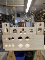
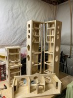
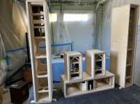
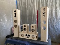
Here are some pictures from the build progress!
Also, while I'm thinking of it. I was going back to the Troels Gravesen site and a lot of their tower speakers have damping on the woofer chamber on all walls, and then just on the back wall of the mid-chamber. Wondering your thoughts on that approach.
Good pro tip, thank you!
Here are some pictures from the build progress!
Also, while I'm thinking of it. I was going back to the Troels Gravesen site and a lot of their tower speakers have damping on the woofer chamber on all walls, and then just on the back wall of the mid-chamber. Wondering your thoughts on that approach.
Attachments
Speaker cabs are looking awesome. Not too hard to tell that it's not your first time working with wood. I've always found it tremendously satisfying when I have designed something and then it starts to come to life - I would hope you are feeling the same. You have come a long way actually from your first post and should be proud of yourself.
I really like a lot of things that Troels does, his xo work in particular looks excellent, but I often think that his cab work could be a little better. It's frequently said that the heart of the speaker is its midrange, so it would follow that it's quite important to get that right. Again, the things that are going to mess it up in terms of the cabinet are panel resonances, internal reflections back to the driver, internal standing waves, general bandwidth panel sound transmission and/or a closed-in, dull or congested sound due to overstuffing or a box that's too small (ie. a less than ideal compliance ratio). The 1st 4 of those things are reduced with more stuffing everywhere in the chamber - standing waves with stuffing in the middle of the box and the rest with the stuffing against the panel walls. The latter problem is hopefully solved with an oversized box which allows lots of room for damping, absorption and empty space still for the driver to breathe. Mind you there's another thread active right now in which the mid is completely and totally stuffed with dense felt like yours and so far the poster has been very happy with the results so perhaps that works well as well? Midrange experiment with Auto sound panel deadener and high density acoustic felt..
So as I said way back, there are definitely different strategies that different people employ and that they are happy with. I've just been telling you what has worked for me so take it with a grain of salt. What you might want to do is do your own experimentation. Try it with less stuffing. Try it with more. Try it the way I've suggested. Which sounds best to your ears with your specific drivers and your specific cabinets? If you can find the time of course. The results may surprise you. They might even surprise me. And if you want to have a look at some objective effects of closed box stuffing, have a look at Dickason's Loudspeaker Design Cookbook, 7th edition page 41 - Empirical Comparison of Box Stuffing Materials.
Thank you very much! Yeah this is not my first rodeo with wood. It has been very satisfying with these cabs tho! Having them come to life and everything. Thank you for the kind words. I have came a long way, but I have had great help!
Okay that does make a lot of sense and is a good reminder about the importance of the mid chamber. Since, I have the removable panels. I will for sure be trying out different approaches and hopefully testing them with instruments as well.
Actually just right now the Amazon felt pads just came in. As a first look I am having doubts, yet that it due to ignorance. All the felt absorption I have researched is all (more or less) flexible and easily moveable. These felt panels I just got are extremely stiff. Like I can knock on them and get an audible sounds from them. So thats odd to me, in my head it seems like they might not absorb that sound as well. Yet! I need to keep in mind that these panels need to absorb the mid range frequencies, like you said around 1kHz is the hardest to do. The description of these panels does tell me that they absorb 1kHz as well of others.
So, it seems like I need to trust the makers on this. As well as that thread you linked is also promising. At first glance they didnt seem to be great, yet with thinking about it more I think they will do just fine or great. Time to experiment! ... soon.
Also I do have the LDC, so I will look back on that discussion of his.
Well, hopefully along with the stiffness there is some density as well. It's that density and lots of it (ie. thickness) that does the better job as you go lower and lower in frequency. would have been nice if the company provided measured noise reduction at different frequencies but you can't ask for everything.
Actually in the link here the company says that it has a density of 300lbs per cubic yard. Also an average absorption coefficient of 0.8 at 5kHz, 2kHz, and 1kHz.
Who knows if theyre being truthful and accurate. But it is quite dense, I'm certain on that haha.
So, I'm still confused about the front baffle for both damping and absorption. I have heard a lot of people saying that it should be clear of anything. I dont think I got a clear thought from you on that, so was wondering that. IMO, I think there should be nothing on the front baffle that is close to the drivers. Maybe a little bit of damping in the mid chambers.
Also, how the heck do you in-set a truncated frame tweeter to be flush mounted? I have been trying to research an answer but cant find one. Im going to cut a circle and try to do it soon as a test. But it doesnt seem like my method with work.
Thanks!
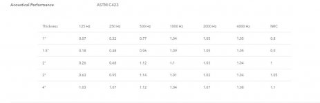
So if I'm doing my calculations properly, that's about 11lb/sq ft, so a stack of about 30 of 12" x 12" x .4" panels should weigh about that much. And just for comparison's sake, below are the sound ratings for the Roxul Rockboard.
I think that most people leave the inside of their front baffles without damping or absorptive material but I have never quite understood this. As long as you continue to leave enough space around the chamfered cutouts for the backs of the drivers to breath, how can it be a negative to begin to absorb any rear energy? Granted, there very frequently isn't a lot of baffle surface area left over after the driver cutouts are done so a little bit of felt isn't going to make much of a difference, but in the case of larger cabinets there can also be a fair amount of bare front baffle area in the woofer chambers so I would add some felt there too and anywhere else you might feel like it but otherwise I wouldn't worry about it. Your 1" baffles add stiffness and a little extra reduction in sound transmission so you are already ahead there. Now again, if I was taking a step or 2 up in driver quality I would probably change my front baffle strategy in a number of ways but for what you are doing, you'll be fine.
Flush mounting an odd shaped driver? You need to make a template out of scrap 1/8" or 1/4" wood. In a nutshell, mount the driver to the template and use the router to follow the outside of the driver frame. Now take the template and line it up on your baffle and follow the inside of the template cutout this time. Adding some lines to the baffle and template can help to line it up properly. Two sided tape may be your friend if clamps or screws won't work to secure the 2 together. Practice a couple of times on more scrap wood. The trick is to get the template cutout exactly the right size and shape based on your router base and bit size. Adding a slightly larger base to the router in step 2 above seems to be the additional necessary step to make it work.
Here's a link with more detail and some pics: Tip: How To Flush Mount Irregular Shape Driver -
Techtalk Speaker Building, Audio, Video Discussion Forum
Attachments
If the felt sheets are not enough, I will try doubling or tripling it. But from what I can tell now, while I staring to line the walls is that it will do a good job. So, we will have to see!
I agree about the absorption on the front baffles. As long as its not choking the drivers or just super close, then yeah why not put some there!
What would you change about your front baffle strategy if the drivers were better quality? like an even thicker front baffle?
Thank you for that link!! I guess I kept searching "truncated frame" but really need to search "irregular shaped driver". Haha those keywords will get ya.
It was a little tricky, but with some practice I got it done!
I'm so close to getting a large milestone done.
Glad to hear the routing worked out. I figured with your experience, you'd get it right.
A better front baffle strategy? I would do more to mitigate the contributions from the mechanical vibrations produced by the movement of the driver's cones which accounts for at least about half the energy that is responsible for panel resonances (so it is said anyways).
So for eg., trying to keep it simple, I didn't mention previously that just because we've put the mids and woofers into separate chambers in your 3-ways, it doesn't mean that mechanical vibrations from the woofers aren't transferred to the mid chamber and vice versa as well as from 1 driver to another. Like I said, cabinet behavior is complex.
So besides the strategies I've outlined for you previously, we might also use some of the following:
- physically separate the woofer cab from the mid/tweeter cab.
- employ 2 woofers on opposite sides of the cabinet in a push/push configuration so that the mechanical forces are working in opposite directions at the same time and therefore cancel each other out.
- mechanically couple the back of the driver magnet to damped interior bracing so that some of the vibrational energy is dissipated by the bracing before it reaches the exterior walls
- mechanically isolate the mid and/or tweeter from vibrations with a material that absorbs energy when under compression. For diy'ers, sorbathane is probably the best material for this.
- mechanically decouple the baffle from the exterior cabinet walls.
- increase panel stiffness with the use of curves and/or tensioned rods.
To get even more complex than these strategies, have a look at what Magico has been doing with many of their speakers by using a double layer front baffle system and have a look at the strategy that Von Schweikert uses for some of their cabinet walls: A Whitepaper: The Audibility Of Cabinet Panel Resonances and Pat. Pend. Method Of Reduction Of Audible Coloration - Dagogo
As an experiment, I recently tried out something similar to both of the above and also tried to do it without a woodworking shop, so using non-standard but easily accessible materials. For the cabinet walls, I used a cement/green glue/recycled tire rubber mats/green glue/fiberglass construction with the outer FG layer a composite of woven FG sheets/sand filled resin with embedded pieces of roofing tile/woven FG. The front baffle was done in 2 layers of FG separated by sorbathane, so again a sandwich of FG on the outsides and sand filled resin in the middle. The first layer was in 2 sections - one for the woofers and 1 for the mid and tweeter with both of these bolted on to the cement layer only. So mechanically isolated from the external FG layer and mechanically isolating the woofers from the mid and tweeter too. So woofers are attached to the 1st baffle layer but the mid and tweeter are attached to the 2nd baffle layer. Just to be sure the mid and tweeter and their method of fastening were also decoupled from the 2nd baffle layer with sorbathane. The 2nd baffle layer is attached to the speaker via threaded rods which run the depth of the cabinet and tighten at the rear. To be clear, the 2nd baffle never makes physical contact with the 1st baffle layer or any layer of the cabinet although the threaded rods do at the back. I might change that if I do it again
It was just a bit of work to put it together however and the cabinets ended up weighing a ton (~150Lb each). Since it was just experimental, I used relatively inexpensive drivers but it turned out so well that I wish now that I had done something different now. Live and learn. The drivers were 4 x Dayton ND91-8, a Wavecor FR070WA02 and a Vifa OT19NC00-04.
To test the cabinet, I put a driver inside the mid chamber, closed it off and then measured the SPL inside the chamber and then outside at the side panel wall trying in both cases to keep the mic about an equal distance from the driver. The attached graph shows the difference between the 2 - minimum attenuation was at about 300Hz and 1500Hz and was about -40dB. I'd call that pretty good.
Pics below:
1- cab + 1st baffle layers
2- cab + both front baffle layers + threaded rods
3- Inside look at the 2nd baffle layer just out of the mold
4- Fit and attachment of the TM with 1st and 2nd baffle layers
A better front baffle strategy? I would do more to mitigate the contributions from the mechanical vibrations produced by the movement of the driver's cones which accounts for at least about half the energy that is responsible for panel resonances (so it is said anyways).
So for eg., trying to keep it simple, I didn't mention previously that just because we've put the mids and woofers into separate chambers in your 3-ways, it doesn't mean that mechanical vibrations from the woofers aren't transferred to the mid chamber and vice versa as well as from 1 driver to another. Like I said, cabinet behavior is complex.
So besides the strategies I've outlined for you previously, we might also use some of the following:
- physically separate the woofer cab from the mid/tweeter cab.
- employ 2 woofers on opposite sides of the cabinet in a push/push configuration so that the mechanical forces are working in opposite directions at the same time and therefore cancel each other out.
- mechanically couple the back of the driver magnet to damped interior bracing so that some of the vibrational energy is dissipated by the bracing before it reaches the exterior walls
- mechanically isolate the mid and/or tweeter from vibrations with a material that absorbs energy when under compression. For diy'ers, sorbathane is probably the best material for this.
- mechanically decouple the baffle from the exterior cabinet walls.
- increase panel stiffness with the use of curves and/or tensioned rods.
To get even more complex than these strategies, have a look at what Magico has been doing with many of their speakers by using a double layer front baffle system and have a look at the strategy that Von Schweikert uses for some of their cabinet walls: A Whitepaper: The Audibility Of Cabinet Panel Resonances and Pat. Pend. Method Of Reduction Of Audible Coloration - Dagogo
As an experiment, I recently tried out something similar to both of the above and also tried to do it without a woodworking shop, so using non-standard but easily accessible materials. For the cabinet walls, I used a cement/green glue/recycled tire rubber mats/green glue/fiberglass construction with the outer FG layer a composite of woven FG sheets/sand filled resin with embedded pieces of roofing tile/woven FG. The front baffle was done in 2 layers of FG separated by sorbathane, so again a sandwich of FG on the outsides and sand filled resin in the middle. The first layer was in 2 sections - one for the woofers and 1 for the mid and tweeter with both of these bolted on to the cement layer only. So mechanically isolated from the external FG layer and mechanically isolating the woofers from the mid and tweeter too. So woofers are attached to the 1st baffle layer but the mid and tweeter are attached to the 2nd baffle layer. Just to be sure the mid and tweeter and their method of fastening were also decoupled from the 2nd baffle layer with sorbathane. The 2nd baffle layer is attached to the speaker via threaded rods which run the depth of the cabinet and tighten at the rear. To be clear, the 2nd baffle never makes physical contact with the 1st baffle layer or any layer of the cabinet although the threaded rods do at the back. I might change that if I do it again
It was just a bit of work to put it together however and the cabinets ended up weighing a ton (~150Lb each). Since it was just experimental, I used relatively inexpensive drivers but it turned out so well that I wish now that I had done something different now. Live and learn. The drivers were 4 x Dayton ND91-8, a Wavecor FR070WA02 and a Vifa OT19NC00-04.
To test the cabinet, I put a driver inside the mid chamber, closed it off and then measured the SPL inside the chamber and then outside at the side panel wall trying in both cases to keep the mic about an equal distance from the driver. The attached graph shows the difference between the 2 - minimum attenuation was at about 300Hz and 1500Hz and was about -40dB. I'd call that pretty good.
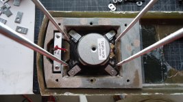
Pics below:
1- cab + 1st baffle layers
2- cab + both front baffle layers + threaded rods
3- Inside look at the 2nd baffle layer just out of the mold
4- Fit and attachment of the TM with 1st and 2nd baffle layers
Attachments

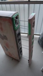
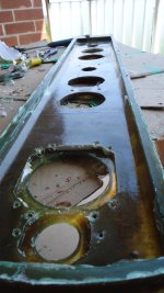
And a couple more pics:
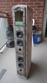
1- Close up of the cab 3 layer wall construction (with a good look at how my FG mold failed me -> corrected with more FG and lots and lots of bondo)
2- Assembled cabs with baffle painted but cab still just with primer.
1- Close up of the cab 3 layer wall construction (with a good look at how my FG mold failed me -> corrected with more FG and lots and lots of bondo)
2- Assembled cabs with baffle painted but cab still just with primer.
Attachments
Sorry it has been so long, I have been non stop on these speakers haha.
But wow that project you did sounds very intense, but dang do i want to hear those bad boys. Judging from you explanation, I'm so intrigued. I can't believe how dang heavy those must have been haha.
Thats pretty awesome that you had the time to experiment like that. Just these wood speakers now are taking up all my time. Mostly due to having to put all the tools away everyday and clean up the dust since Im in the garage. And now its cold so sanding is take each speaker at a time outside.
Anyways, your finished product of those cabs looks amazing. Like straight out of a factory clean finish and look to them. Thats something Im trying to strive for right now and is also taking a lot of time. Is while assembling Im noticing how when some cuts are not perfectly square or straight, then towards the end of the build Ill have some problems that are so frustrating. Like the side of one of the towers not being long enough by like a 1/16" of an inch, but thats noticeable! Not to mention will make the tower not level.
Other problems as well. But im trying my best to make everything straight and square.
Also, I agree lots and lots of bondo haha
Yesterday I was in the middle of doing the chamfers on the outside of the speakers and my router completely died on me. So when I can get that done, I've got all the felt cut and ready to go and thatll be put in after chamfers are done. Then the rest of the absorption since the roofing tiles are all in right now.
Then xo and paint them!
So, while Im spewing everything on my mind, I've been thinking a lot how much time the xo would take to design. I've been reading up in it some and with my knowledge already about filters I dont think it would be too extensive. But yet again, I didnt think that about the design of the speakers and that took awhile. Which is fine, but Im always trying to schedule things and plan accordingly ya know. But also, wanting to take the time to fully learn as much as I can about it.
So when we get to that point, we shall see haha.
Happy Holidays!
Glad to hear you are making progress. Five speakers is a big project so don't be too hard on yourself if you aren't quite meeting your schedules. Better to keep the construction quality high than to start looking for shortcuts if you can.
So once you get the speakers assembled, you'll need to measure the FR and the impedance for each driver. I use REW. Unless you've already got something that will do the job, you'll need to make a limp jig to measure impedance. Very simple. You'll find more info in the REW 'Help' window and/or just google 'limp jig' images. The measurements work with older desktop soundcards but most laptops will require an external soundcard because you need separate audio out (headphones) and audio in (mic) inputs to do the impedance measurements with the jig. For the more serious minded, there is also Dayton's Dats system.
To design the actual xo's doesn't take me too long although I like to take a couple of days and maybe try different approaches when I can. To help the learning process, it perhaps might be beneficial for me to post the XSim files using the spec sheet data just for you to start practicing. Give me a little time on that.
But once the real xo's are designed, it's also best to sit and live with and listen to the speakers and fine tune the xo's as necessary. You might actually want to take at least a couple of weeks for that but that will be up to you.
Happy holidays as well.
I'm a little busier than usual right now with Xmas but I finally found some time to put together the files for your rear TM's which is a good place to start in terms of xo design. That is if you can find the time to to give it a go right now too!
So I've attached a zipped XSim file. Just unzip it and it should be ready to go. The files include the baffle and box info for both drivers for the rear speaker so it should be pretty close to reality but probably not perfect.
So some XSim instructions:
1. I always start every XSim session the same way - in the FR graph in the 'Curve' drop down menu, select black as the system response and turn off system phase. Select S1, the tweeter, and make it red with phase turned on. Select S2, the woofer, and make it blue and turn on phase.
2. Under the 'Scale' drop down menu, select 10Hz as the min frequency and select about 80db as the vertical center (or whatever is necessary) to see what is happening at least about 40dB below the fundamentals.
3. You'll see that I've included 4 extra drivers up top which are intended to function as your target curves. The 1st two are Linqwitz-Riley 2nd order (LR2) at about 2300Hz* and the last 2 are LR4 at the same xo frequency. Try just 1 at a time with the intent being to try to match the driver FR curves to the target curves. To activate these curves, under 'Curves', select S3 and S4 (driver only). I like them in grey as that color seems less distracting. (Yes, I'm a little anal about all this as uniformity makes it much easier for me to quickly interpret the graphs each and every time.)
4. Start with the woofer because this sets the sensitivity level of the speaker as a whole. And it's the woofer response at about 200Hz that will determine this level. So how I do this in XSim is I adjust the amp level so that the woofer level and the target curve level are about the same SPL at about 200Hz (I generate the target curves in Response Modeler and then import them into XSim and that program defaults to 90dB, if you are curious.) For a single RS150P-8A, that was about 3W which I've already done for you. (This is meaningless btw; it's a just a method that works in XSim)
So now start working L1 and C1 to match your blue curve to the grey LR2 LP target. And here is a general xo tip: try to make the 1st component, the series component in the xo do most of the work, if possible (holds true for every driver, not just the woofer). So I'll generally adjust L1 1st a little bit and then C1. I'll adjust C1 until the curve usually starts to increase somewhere above the 'knee' of the curve, in this case around about 1200Hz. That means it's a little too high in relation to the L1 value. So then I'll adjust L1 until it flattens out again and so on and so forth until you've got a decent match to the target curve. Another tip would be to always try to keep C1 as low a value as possible (this has to do with keeping as little current going to ground as possible).
5. Then move on to the tweeter. I've included 2 series resistors, R1 and R2, to adjust the tweeter level both before and after the tweeter xo filter as they can have slightly different effects on the shape of the response. Sometimes just 1 is enough. Sometimes both are good. And sometimes an L-pad (series and parallel resistors after the xo filter) is better, maybe sometimes in combination with R1 too. Or maybe not. It's mostly just a trial and error kind of thing to see what works.
So with the tweeter, I might start by shorting the 2nd cap, C3 (or changing it to a fairly high value) and then working with C2 and L2 sort of in a similar but opposite way as with the woofer. Again the tip here would be to keep L2 as large a value as you can for the same reasons as C1 above.
6. The sim is set up with what I would expect to work for a 2-way btw. So far I've had you ignore looking at the summed response but if you've managed to get the driver responses to match the target curves and the summed response happens to still look like hell, then it's time to start looking at the phase response too. Sometimes the tweeter polarity needs to be reversed and that will fix things and sometimes it does a better job but still not good enough. So it's important to note that the xo is trying to do more than just produce a decent summed FR. You should also be trying to align the driver phase in the xo region and you should be trying to keep a reasonable summed impedance response all at the same time. And it doesn't hurt to try and keep an efficient current consumption at the same time but don't worry about that for now. I've already helped you with that without you even realizing it.
7. So if the phase isn't quite aligned properly, now is the time to start bringing C3 into play to try and make that happen. Sometimes this alone will work out but usually now is also the time that you have to start to fine tune more than a few of the components to get both the FR and the phase alignment looking good. Another trick is to throw a resistor in series with the filter shunt components, so with either L2 or C1 or perhaps both and watch how it will fine tune the phase. Luckily in this instance you don't need to do that. I don't think.....
8. You also want to keep driver "unpleasantness" like cone resonances or driver harmonic distortion sufficiently below the level of the fundamental. In this case the only troublesome spot is with the woofer at about 5400Hz which looks like a bit of a resonance peak. There are more than a couple of ways to deal with this problem but perhaps the easiest and simplest is with a 'tanking' cap added to L1 in parallel. You will see the effect as soon as you move C4 into that position with L1. Then adjust the value until it hits right about at 5400Hz.
9. So that's with 2nd order filters. Note that we are talking about the acoustic shape of the curves here and not just the electrical order of the filters. But maybe 4th order acoustic might be better. So save your file for your 1st attempt and then try again using the LR4 target filters. It'll be good practice.
* The choice of a xo frequency and the steepness of the xo slopes depends on a few factors. Probably most importantly, we want to keep the xo frequency reasonably far from the tweeter resonant frequency (or to put it another way, we want to keep the tweeter resonant frequency sufficiently below the level of the fundamental, I'd probably say a minimum of 30dB) and we want to cross the woofer over before it's off-axis response starts to differ too much from its on-axis response, ie. before the off-axis response at 45 degrees is more than about 3dB below the on-axis response. Harmonic distortion and cone resonances can also factor into these decisions.
I always treat the target curves as flexible btw. They should not be set in stone. Frequently, you have to let the drivers tell you where they more or less want to be crossed over at and not exactly where you want them to be. So it's a little more reasonable to think of the target xo frequency as a range and not as a specific frequency.
Let's see how you get on with that to start off with. If you have the time. lol.
Attachments
Yeah 5 speakers is quit a large project, much larger than I even anticipated. But that's okay!
I do have REW and will figure out that limp jig soon. Was just researching it a little.
The good thing is, I do not have a deadline anymore for these speakers. Realizing that right now I cannot set a time to finish these is nice haha.
I totally understand also, these Holidays have been very busy.
I really appreciate the Xsim instructions! I will be diving into these this week hopefully and will get back to you!
I have been spending lots of time on the speakers with sanding and bondo. They are finally done with bondo and I will be doing a higher grit sanding tomorrow as the final sanding! (finger crossed) haha
Also had to set up a retractable plastic wall in my garage since it is now snowy/cold and can no longer sand outside.
Will be posting pictures of them once I take some pictures haha
So, then I will put in the felt absorption that is already cut for all the walls. Then the rest of the absorption, then I will test them!
Then I will start panting them. In between coats I will try and work on the xo.
One big thing that always slips my mind and was never in my CAD designs was a grill frame and cloth cover. I keep forgetting my brother wants one and I am will researching and figuring out how I can do that with the materials I have or can get. So, speaker testing might be pushed off if I decide to tackle that first this week.
Hey Keil, happy new year.
Yea, you've set yourself a very ambitious first time project and with a (former) deadline at a very busy time of year for most people. I have found in similar situations that it can be very helpful to take a small break to avoid burnout and then return with fresh energy. Good to know things are still moving along and that the deadline has been removed.
I've never actually built grills for my speakers so I'm not going to be much help there. I have a particular fondness for the aesthetics of the drivers lined up on the baffle and I don't live with children or pets either. I've seen many people these days using magnets as the method of attachment - I would assume they have less chance of breaking like the kind of ball and socket attachments that have been used in the past.
I do have a pair of old Paradigm surrounds still hanging around with grills - they are just 1/2" thick pressboard about 3/4" wide at the top and bottom and about 5/8" thick at the sides. The backs are just flat but the front outside edges are chamfered (like a picture frame) and the front inside edges as well. The grill cloth is just glued on. Ball and socket type attachment and yes a couple of them broke over the years.
Happy New Year Chris!
Yeah I have been taking the Holidays as a break. Though I did spend a few days doing some small stuff, for the most part I set it aside.
Yeah I too enjoy the drivers lined up on the baffle as well. I have been having some conversations with my brother recently and have come to the conclusion that the grill covers will not be done. Just too much work to be done with that right now and also there is no way I can ensure that the frame will not crack and break over time. Even though I was planning on the magnet idea! My former roommate had a pair of Klipsch towers that had magnets and it was great!
Might be little bit before I get to the xo stuff though, I am getting ready for my twin brothers wedding this weekend. Especially in the midst of covid, things are challenging to plan.
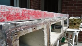
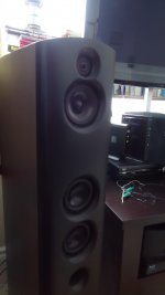
But here are a few pictures of where my progress is! The colored markings on the speakers were for me to quickly know there to bondo since the dry time is very fast. They'll never been seen after painted anyways.
So yeah I have the primer and paint bought, as well as a spray gun! So when sanding is 100% I will be covering the floor and workbench in plastic, putting a box fan backwards in the window, and painting these puppies!
Yeah I have been taking the Holidays as a break. Though I did spend a few days doing some small stuff, for the most part I set it aside.
Yeah I too enjoy the drivers lined up on the baffle as well. I have been having some conversations with my brother recently and have come to the conclusion that the grill covers will not be done. Just too much work to be done with that right now and also there is no way I can ensure that the frame will not crack and break over time. Even though I was planning on the magnet idea! My former roommate had a pair of Klipsch towers that had magnets and it was great!
Might be little bit before I get to the xo stuff though, I am getting ready for my twin brothers wedding this weekend. Especially in the midst of covid, things are challenging to plan.
But here are a few pictures of where my progress is! The colored markings on the speakers were for me to quickly know there to bondo since the dry time is very fast. They'll never been seen after painted anyways.
So yeah I have the primer and paint bought, as well as a spray gun! So when sanding is 100% I will be covering the floor and workbench in plastic, putting a box fan backwards in the window, and painting these puppies!
Attachments
Awesome. Absolutely awesome!
Your brother is going to owe you big time.
Stay safe at the wedding.
Cheers
Your brother is going to owe you big time.
Stay safe at the wedding.
Cheers
Thank you very much! And haha yeah he does.
So Im starting to put the absorption in and I have finished all the felt.
Now I will start putting in the wiring and also the rest of the absorption.
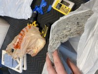
Question, I have ran across the medium density cotton sheets that came in a package to insulate the food with the dry ice. The picture is attached.
What are your thoughts in using that instead of the foam mattress for the mid chambers?
Also thank you, we all stayed safe thankfully at the wedding. But, only time will tell if any of us contracted the virus. Hopefully not.
So Im starting to put the absorption in and I have finished all the felt.
Now I will start putting in the wiring and also the rest of the absorption.
Question, I have ran across the medium density cotton sheets that came in a package to insulate the food with the dry ice. The picture is attached.
What are your thoughts in using that instead of the foam mattress for the mid chambers?
Also thank you, we all stayed safe thankfully at the wedding. But, only time will tell if any of us contracted the virus. Hopefully not.
Attachments
- Home
- Loudspeakers
- Multi-Way
- First-Timer Home Theater Speaker Build