Yeah it does looks good but I ended up going with the foam mattress since it was always the plan. Ill save those for another project sometime.
Next week will be testing and starting that xo finally!
Also, I have a question about the xo. Should I put either the felt absorption or the poly-fill around it when its in the speakers, or just leave it untouched?
Next week will be testing and starting that xo finally!
Also, I have a question about the xo. Should I put either the felt absorption or the poly-fill around it when its in the speakers, or just leave it untouched?
Well, if you mount the xo's on some kind of board and then place that over your fill, the fill won't really be doing a very effective job will it?
So place the absorption materials over the xo's if you can. This can be a bit of a pain as you work at fine tuning the xo though, so most people will keep the xo external during that process, often running the wires out through the port until the xo has been finalized. Then put it into the cabinet and cover with your fill.
So place the absorption materials over the xo's if you can. This can be a bit of a pain as you work at fine tuning the xo though, so most people will keep the xo external during that process, often running the wires out through the port until the xo has been finalized. Then put it into the cabinet and cover with your fill.
Yeah that makes a lot of sense haha. Putting the wires through the port though is a great idea! Since taking out the back of the speaker every time would be a pain. Thank you.
So, I've been researching the limp jig a little bit and my only question to it is this:
I've already tested the speaker impedance without a limp jig, I did it from instructions from the LDC. So, why can I not do that same method here while they are in the boxes?
Also, if I need a special sound card for the mic input to REW. Can I not just hook up my Focusrite interface and plug in my DBX RTA-M for the REW measurements?
Btw, I do have REW. I used it briefly in a class, but I dont know it too well. I will get more acclimated with it soon.
I have not looked into the Xsim stuff yet because it seems like I need these measurements first.
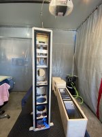
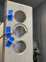
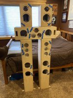
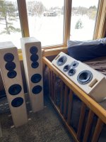
Also, here are some update photos of the speakers. Putting in the absorption took longer than I anticipated, as per usual haha. But its all done and the drivers are in, ready to test.
I've already tested the speaker impedance without a limp jig, I did it from instructions from the LDC. So, why can I not do that same method here while they are in the boxes?
Also, if I need a special sound card for the mic input to REW. Can I not just hook up my Focusrite interface and plug in my DBX RTA-M for the REW measurements?
Btw, I do have REW. I used it briefly in a class, but I dont know it too well. I will get more acclimated with it soon.
I have not looked into the Xsim stuff yet because it seems like I need these measurements first.
Also, here are some update photos of the speakers. Putting in the absorption took longer than I anticipated, as per usual haha. But its all done and the drivers are in, ready to test.
Attachments

Last edited:
Yes for sure, if you already have a successful way of taking impedance measurements by all means use that. A lot of different ways to skin a cat when it comes to this whole endeavor of speaker building.
So the mic I use just has a simple usb connection that I've just plugged directly into both my old desktop computer and my current laptop computer, no external soundcard necessary. The problem is with Limp jig type impedance measurements with computers (mostly laptops?) that don't have both separate input and output connections. But that might not be a worry for you.
That Focusrite interface is beyond my experience but if it works with that mic and your computer..... then it should do fine.
REW is just 1 measurement program btw. There are more than a few others. Personally I found it to be the easiest to set up and use of the couple that I've tried so that's the one I've stuck with. Took me more than a couple of years to figure out that it's also got some nice file manipulation abilities that are super fast and don't require Excel.
Speakers are looking great too!!
Okay sounds good! Then I will go with what I have done before.
As far as using REW and the mic, what measurements do I need to obtain? Am I needing a FR from all the drivers in the boxes?
Also, does there need to be an input and output in order for REW to send a signal to the speakers and then the mic to receive for measurements?
So, before crossover design we need:
- Impedance curves of all drivers in the boxes
- Frequency Response of all drivers in the boxes?
Is there anything I am missing?
Also, thank you very much! It's nice to see them get much closer to being finished. Cannot wait to listen to these!
Also, does there need to be an input and output in order for REW to send a signal to the speakers and then the mic to receive for measurements?
Yes. I use the headphones output from my laptop to my computer speakers (self powered). Then all I need to do is plug my mic into a usb port, place it in front of the speakers and run REW to get a measurement. To do measurements on a set of passive speakers, I take the headphone output over to me AVR receiver and plug it into the 1/8" auxiliary input it has on the front. Then I just make sure that I bypass all the internal processing and run them fullrange for an accurate REW measurement. Actually, you need to make sure there is no internal eq processing going on with your computer too. With an older receiver without that aux input, I needed to create some wiring that took the 1/8" jack from the computer and turned it into an RCA connector that I could attach to the rear RCA aux input. What you need to do I guess is going to depend on how that mic/interface gets inputted into your computer.
In terms of the FR measurements, there are more than a few different methods (who would have guessed that?) but for your first effort I think it's best to keep it as basic as possible. Which to me means taking single on-axis FR measurements without phase info (you can do off-axis measurements later if you want), extracting driver phase mathematically (which is what REW does anyways) and finding the relative acoustic centers of the drivers with another series of measurements.
So yes, take impedance and FR measurements for each driver. You can conceivably just use 1 of the speakers when they come in pairs but it wouldn't hurt to do every single driver in every speaker to both ensure the consistency of your measurements and to make sure that the drivers and the interior chamber treatments are consistent across the board.
Put the mic at the tweeter height and then don't move it for all subsequent measurements on that particular speaker. Don't touch the amp level either. Record the actual distance of the mic from the baffle for the paired speakers because you'll want to repeat that same distance for the corresponding pair. For farfield measurements, the distance should vary depending on the number of drivers in the speaker or in other words the distance between the tweeter and the other drivers. For your surrounds, just 2 drivers closely spaced, something around 20"-24" is just fine. For farfield with the 3-way speaker, something closer to 36" would be better.
I think I already linked Jeff Bagby's measuring paper but just in case here it is again: In-room Quasi-Anechoic Measurements
For finding relative acoustic centers, here are 2 more links:
Box
Speaker acoustic center - How to find it | Audio Judgement
The 1st link does it in reference to a different xo program but is worth reading anyways. The 2nd uses XSim which will be more helpful. I've ended up using a combination of these 2 methods in that I take the individual driver measurements and then I take combined driver measurements in pairs wired in parallel as opposed to taking the combined measurement of the whole 3-way.
So for your 2-way, set up the mic, take the individual driver measurements and then take the pair together.
For the 3-ways, take each driver individually and then take the paired measurements of the TM(top), TM(bottom), TW(top) and TW(bottom). For the CC, I might be willing to measure the 2 mids together as 1 driver because you have them so close together and symmetrical with the tweeter too. Maybe you could do that for the tower mids too but for the 1st time, I think you should do them separately. Or do it both ways and compare. That means then that the paired measurement(s) would be the TMM and that you have to do the impedance measurement of the pair together as well. Because I'm a finicky sort, with 3-ways I take an extra paired measurement of the mid and woofer which will allow me to double check for accuracy.
Confused yet? 😱 Actually taking the literal measurement is the easiest part of the whole thing. Getting everything set up properly and keeping it all straight is the harder part. Well, for me anyways.
Yeah the Focusrite has a headphones out that I can pas through to a receiver. So that'll work great!
Yeah I think for now I will only do on-axis responses, possibly off axis later.
I will be taking impedance measurements of all drivers in pairs and then taking the average.
So, even if I am measuring the FR of the bottom woofer on the tower, I should have the mic 36" away and at the height of the tweeter? Wouldnt that be off-axis for the woofer then?
So all the measurements I need are:
Impedance:
- All individual drivers. But do I need impedance of the tweeter since it
doesnt rely on the box?
- Impedance of all pairs. So, the two Mids in the Towers and CC. Then also
the two woofers in both the Tower and the CC. Yet, the woofers in the
CC dont share an internal volume together so should that measurement
even matter?
Frequency Response:
- The FR of all drivers individually.
- For the Rears the mic is at tweeter height and ~22" away.
- For the Towers and CC, the mic is tweeter height and ~36" away
- The FR of the two pairs, TM(top) TM(bottom) TW(top) TW(bottom).
Corresponding left right for the CC as well.
- The FR of the three pairs, TMM and TWW
So, when I do the pairs, I just put all of them in parallel and they receive the same signal at the same time? Correct me if I'm wrong, but I thought it was not good for the tweeter to receive lower frequency signals since it cannot handle those low frequencies at all.
Also, in REW should I just do a 'Room Sim' for these responses?
Actually, after the impedance measurements Ill look up tutorials on REW to get better at it.
Also, yet another also haha sorry, but how high of a frequency do we need for the impedance results? Last time I did the testing I could only go up to 3kHz until the method I use was not accurate anymore.
Thank you for the links as well! I will be reading these in preparation.
Last edited:
So, even if I am measuring the FR of the bottom woofer on the tower, I should have the mic 36" away and at the height of the tweeter? Wouldnt that be off-axis for the woofer then?
Yes and yes. The mic should be on the listening axis which is generally at tweeter height which means that every driver is listened to vertically off-axis in reality except for the tweeter and so that's how we should measure them. Plus the moment you move the mic, it becomes more likely that the relative SPL levels might be off. Granted that the listening distance is usually going to be greater than the mic distance but we generally don't worry about it.
Correct me if I'm wrong, but I thought it was not good for the tweeter to receive lower frequency signals since it cannot handle those low frequencies at all.
Also correct. For the purposes of getting the acoustic centers, we are only interested in the frequency ranges that overlaps so you can simply set REW to start the measurement at a comfortable frequency for the tweeter. Some say 200Hz. Maybe safer up at 500Hz. Plus the measurements don't have to be taken at really loud volumes which also makes it easier on the tweeter.
Measurements from 20Hz to 20kHz will be fine.
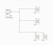
In terms of the measurements, go through the documents I linked and they might answer a few of your questions. But maybe a visualization will help. Attached below are what the xo wiring is going to look like in XSim for each speaker, surround 1st, then the towers and then the CC. So for each of those drivers you will need a FR and an impedance measurement and a relative acoustic center measurement to sim the xo's. The exception is the CC where you can see that I only have 1 driver for the mids which means you can do the 2 mids measured together for both the FR and the impedance because the responses should be exactly the same - they are symmetrical on the front baffle so baffle diffraction is the same for each driver which won't be the case for the other mid and woofer pairs. Or you could just as easily do them individually as well. Some of the relative acoustic center measurements will be the same too - more info on that below.
For impedance: yes all individual drivers except the CC mids which you can do as a parallel pair. Include the tweeter because who knows if the spec sheet is exactly right or not.
For FR: let's think of it in 3 parts.
Farfield: with 1 mic position
- all individual drivers except the CC mids which can be done as a pair wired in parallel again.
Nearfield: the mic gets moved for each driver. These are just for LF responses so the tweeters don't get done.
- the woofer in the TM surround
- just pick 1 of the mids and woofers in the towers
- 1 of the mids and both of the woofers in the CC
Relative Acoustic centers: with mic in 1 position again.*
- each individual driver, except the CC mids in a pair again
- the surround TM pair
- one TM pair and each TW pair in the towers (the mids in the tower are each the same distance from the tweeter so the relative acoustic center locations will be exactly the same for each one)
- the TMM and 1 of the TW pairs in the CC (only 1 TW pair is necessary for the same reason as the TM's in the towers)
Optional:
- in the towers, the bottom mid and top woofer pair and the bottom mid and the bottom woofer pair
- in the CC, a MMW pair, either the left or the right W
*You can use the same individual driver farfield measurements from above keeping the mic in the same location for the pairs or you can choose to take them all once again in which case it doesn't really matter where the mic is as long as it's always kept in the same spot for each individual speaker.
For the CC and the surround, you may want to get them up on a stand that will raise them up off the floor a meter or so and also not present much a baffle signature if possible.
For all the tweeter measurements, start up near that 500Hz mark, plus or minus.
The 22" and 36" are flexible but you get the idea.
I can appreciate that that might be confusing. Don't hesitate to ask for more clarification.
Attachments
I will ask for more clarification this week when I get to the FR testing.
Right now it is making sense and those links you sent are also very helpful!
But I know when I start that, I'll most likely have questions haha.
For now though, I have done the impedance testings and the drivers are sounding good! Also the two pairs of towers and rears have similar responses between them which is good!
Everything seems to be checking out, but the tower woofer responses are a bit of a mystery to me.
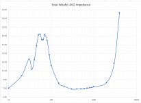
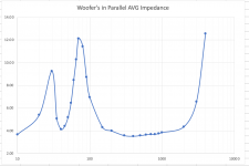
So the first picture is total average of all four woofers individually tested. There seems to be three resonance peaks which is odd. I would have only thought there would be two of them. Plus, keep in mind that the graphs on the individual woofer responses look the exact same.
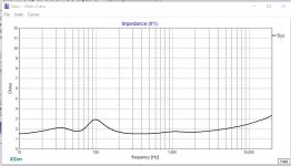
But, the second picture is of the woofers in parallel impedance response. When in parallel, they then have two clear peaks.
I just dont know if this is a problem or even how to 'decipher' this haha.
Any thoughts?
Also, I will email the Excel file to you so you can take a closer look at the data if desired.
Right now it is making sense and those links you sent are also very helpful!
But I know when I start that, I'll most likely have questions haha.
For now though, I have done the impedance testings and the drivers are sounding good! Also the two pairs of towers and rears have similar responses between them which is good!
Everything seems to be checking out, but the tower woofer responses are a bit of a mystery to me.
So the first picture is total average of all four woofers individually tested. There seems to be three resonance peaks which is odd. I would have only thought there would be two of them. Plus, keep in mind that the graphs on the individual woofer responses look the exact same.
But, the second picture is of the woofers in parallel impedance response. When in parallel, they then have two clear peaks.
I just dont know if this is a problem or even how to 'decipher' this haha.
Any thoughts?
Also, I will email the Excel file to you so you can take a closer look at the data if desired.
Attachments
Last edited:
Hey Keil,
I hope you weren't beating yourself up too badly trying to figure out where you made a mistake on the tower woofer impedance measurements because the mistake wasn't your's, it was mine. My apologies. I gave you some bad instructions.
Let's think about what's going on with a pair of woofers in 1 chamber vs a single driver. First we know that both drivers together are going to need twice the volume as a single driver and that to keep the same tuning, we are going to have to change the port length. And second, we know that loading a driver into a box is going to change both it's FR and impedance response in the low frequencies only.
So, when you measure the impedance of just a single woofer in your situation, the box will now be too big and the port will be wrong so the tuning will change and in fact that 2nd woofer that isn't being used will act something like an improperly tuned passive radiator creating a bit of a mess down in the LF region as you have discovered. But only in the LF region as you can see that the shape of all the tower woofer impedance measurements above about 100Hz are exactly the same.
That's my bad I didn't pick up on that - I should have told you that with all the drivers that are paired up in a single chamber, you need to measure the impedance with both drivers wired together in parallel. This'll be true for the mids as well.
A couple of other points.
1. Before measuring, it's always a good idea to work the drivers in for a bit - it will help to loosen the suspension and will change up some of the TS parameters a bit. I don't know if perhaps you have already done that. If not, running a LF signal through the mids and woofers (skip the tweeters 😱) for a few hours so you get some decent cone movement, but not extreme, will do the trick.
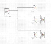
2. You actually want to be really careful if you wire up all the drivers together without a xo for the towers and the CC. That's essentially 3 x 4ohm drivers that you are wiring up in parallel which is going to give you a summed impedance response that is below 2ohm. Play that loud and/or for too long and your amp may be 1 unhappy customer. Actually, some amps may not be happy with it, period. That's pic 1 below. The xo btw acts as a frequency dividing network so that each driver or set of drivers is operating more or less individually when they have a xo filter in front of them even though they are all still wired up in parallel.
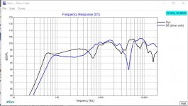
3. Just for a visual reference, the 2nd pic shows you what you were more or less hearing when the towers and surrounds were wired up without xo's. Somewhat similar but with definite differences. There are actually fairly deep nulls in different places but if you heard them as quite similar, that just goes to show that generally speaking, we are less sensitive to FR nulls vs peaks.
4. So besides the LF error in the single impedance measurement - which isn't really an error at all - there are 2 things that are standing out to me as not quite right. First is that all the impedances are rising very steeply above about 2000Hz which is not consistent with the spec sheets. Not even close actually. I'm not exactly sure why, but the fact that this is consistent with all the measurements you emailed me, I suspect it might be something to do with methodology. I wonder if the tweeters are like that too?
I'm not familiar with the technique or all the equipment I think you are using so it's hard for me to comment, but as a test for impedance, measure a resistor of any value if you happen to have 1 handy. The measurement should be a straight line right across the FR. If it isn't we know that the problem is indeed a measurement one. Or measure the tweeter impedance. If it's spiking in a similar fashion, I think we can be pretty sure that it doesn't have anything to do with the drivers.
5. The 2nd thing I'm not sure about is the woofer tuning in the towers. It's not quite exact, but if you look at the frequency of the lowest point in between the 2 impedance peaks of a vented driver, that'll be about the tuning frequency. It looks about right for the woofers in the CC and the surround, but it's down around 40Hz for the towers which isn't making sense to me. But maybe let's not worry too much about that for now.
So what I'm thinking is that let's try to figure out what's going on with the impedance measurements first and let's just keep it as simple as we can so let's just work with the TM surround for now. Then we'll do the FR measurements and then the AC measurements on it and then we'll move on to the other speakers. Make sense?
I hope you weren't beating yourself up too badly trying to figure out where you made a mistake on the tower woofer impedance measurements because the mistake wasn't your's, it was mine. My apologies. I gave you some bad instructions.
Let's think about what's going on with a pair of woofers in 1 chamber vs a single driver. First we know that both drivers together are going to need twice the volume as a single driver and that to keep the same tuning, we are going to have to change the port length. And second, we know that loading a driver into a box is going to change both it's FR and impedance response in the low frequencies only.
So, when you measure the impedance of just a single woofer in your situation, the box will now be too big and the port will be wrong so the tuning will change and in fact that 2nd woofer that isn't being used will act something like an improperly tuned passive radiator creating a bit of a mess down in the LF region as you have discovered. But only in the LF region as you can see that the shape of all the tower woofer impedance measurements above about 100Hz are exactly the same.
That's my bad I didn't pick up on that - I should have told you that with all the drivers that are paired up in a single chamber, you need to measure the impedance with both drivers wired together in parallel. This'll be true for the mids as well.
A couple of other points.
1. Before measuring, it's always a good idea to work the drivers in for a bit - it will help to loosen the suspension and will change up some of the TS parameters a bit. I don't know if perhaps you have already done that. If not, running a LF signal through the mids and woofers (skip the tweeters 😱) for a few hours so you get some decent cone movement, but not extreme, will do the trick.
2. You actually want to be really careful if you wire up all the drivers together without a xo for the towers and the CC. That's essentially 3 x 4ohm drivers that you are wiring up in parallel which is going to give you a summed impedance response that is below 2ohm. Play that loud and/or for too long and your amp may be 1 unhappy customer. Actually, some amps may not be happy with it, period. That's pic 1 below. The xo btw acts as a frequency dividing network so that each driver or set of drivers is operating more or less individually when they have a xo filter in front of them even though they are all still wired up in parallel.
3. Just for a visual reference, the 2nd pic shows you what you were more or less hearing when the towers and surrounds were wired up without xo's. Somewhat similar but with definite differences. There are actually fairly deep nulls in different places but if you heard them as quite similar, that just goes to show that generally speaking, we are less sensitive to FR nulls vs peaks.
4. So besides the LF error in the single impedance measurement - which isn't really an error at all - there are 2 things that are standing out to me as not quite right. First is that all the impedances are rising very steeply above about 2000Hz which is not consistent with the spec sheets. Not even close actually. I'm not exactly sure why, but the fact that this is consistent with all the measurements you emailed me, I suspect it might be something to do with methodology. I wonder if the tweeters are like that too?
I'm not familiar with the technique or all the equipment I think you are using so it's hard for me to comment, but as a test for impedance, measure a resistor of any value if you happen to have 1 handy. The measurement should be a straight line right across the FR. If it isn't we know that the problem is indeed a measurement one. Or measure the tweeter impedance. If it's spiking in a similar fashion, I think we can be pretty sure that it doesn't have anything to do with the drivers.
5. The 2nd thing I'm not sure about is the woofer tuning in the towers. It's not quite exact, but if you look at the frequency of the lowest point in between the 2 impedance peaks of a vented driver, that'll be about the tuning frequency. It looks about right for the woofers in the CC and the surround, but it's down around 40Hz for the towers which isn't making sense to me. But maybe let's not worry too much about that for now.
So what I'm thinking is that let's try to figure out what's going on with the impedance measurements first and let's just keep it as simple as we can so let's just work with the TM surround for now. Then we'll do the FR measurements and then the AC measurements on it and then we'll move on to the other speakers. Make sense?
Attachments
Last edited:
Oh no I was not beating myself up about that, I was just very curious and confused what was going on. But that makes so much sense now how with one speaker tested, the other will act as an improperly tuned passive radiator.
So to hit on your points, numbered in accordance to your numbered points:
1. After reading about loosening the drivers in the LDC and thought it was an odd but interesting concept. So, I did just that with one of the woofers many months ago. I played I think 60Hz through it on an open baffle for about 5 hours, then tested it again. I got the same results as before, so I didnt think it was too necessary. I tried researching if Dayton Audio already does that for their drivers and could not find anything on it. But in the end, it didnt change the impedance response for me.
4. Yeah that is a good point about the impedance rising around 24ohms at 4kHz. That could definitely be due to my method.
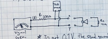
So, I do what you described. The circuit it attached below.
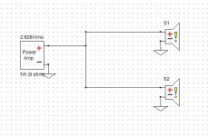
I have the 10 ohm resistor to find the voltage to have at point (A). Using a 0.1 volt scale, so 0.1Vrms equals 10 ohms. That voltage is 3.335Vrms. So, I actually had my DMM at point A to make sure the input was always at 3.335Vrms since the voltage changes due to the change of the load (i.e. the driver). Then I have my oscilloscope at nodes X and Y to read the voltage at the driver.
So, when I change the frequency at my signal generator, I slightly change the voltage from the SG to make sure my DMM reads 3.335V. Then, I look at my oscilloscope and read the voltage to find the impedance. So, if the oscilloscope read .1245Vrms, then the impedance is 12.45 ohms.
But, after 3kHz my signal generator cannot output enough voltage to keep point (A) at 3.335Vrms. So at 4kHz I used a 0.05Vrms scale (0.05Vrms = 10 ohms). That voltage is 1.685Vrms at point (A) then. So when I read say 0.1085Vrms on my oscilloscope, then I multiply that number by 200 to get the impedance. Now, this is where I could have for sure went wrong. Though, do we need an impedance reading above 4kHz anyways?
5. That is a good point how the towers tuning looks to be around 40Hz, but I could shorten the port length to raise that tuning couldnt I? Or maybe a little stuffing in the port to choke it a little.
I hope the testing I did was right because that method takes a long time 😱
Though, of course I want to do it right! With no deadline to worry about, I got the time to do it again😎
So to hit on your points, numbered in accordance to your numbered points:
1. After reading about loosening the drivers in the LDC and thought it was an odd but interesting concept. So, I did just that with one of the woofers many months ago. I played I think 60Hz through it on an open baffle for about 5 hours, then tested it again. I got the same results as before, so I didnt think it was too necessary. I tried researching if Dayton Audio already does that for their drivers and could not find anything on it. But in the end, it didnt change the impedance response for me.
4. Yeah that is a good point about the impedance rising around 24ohms at 4kHz. That could definitely be due to my method.
So, I do what you described. The circuit it attached below.
I have the 10 ohm resistor to find the voltage to have at point (A). Using a 0.1 volt scale, so 0.1Vrms equals 10 ohms. That voltage is 3.335Vrms. So, I actually had my DMM at point A to make sure the input was always at 3.335Vrms since the voltage changes due to the change of the load (i.e. the driver). Then I have my oscilloscope at nodes X and Y to read the voltage at the driver.
So, when I change the frequency at my signal generator, I slightly change the voltage from the SG to make sure my DMM reads 3.335V. Then, I look at my oscilloscope and read the voltage to find the impedance. So, if the oscilloscope read .1245Vrms, then the impedance is 12.45 ohms.
But, after 3kHz my signal generator cannot output enough voltage to keep point (A) at 3.335Vrms. So at 4kHz I used a 0.05Vrms scale (0.05Vrms = 10 ohms). That voltage is 1.685Vrms at point (A) then. So when I read say 0.1085Vrms on my oscilloscope, then I multiply that number by 200 to get the impedance. Now, this is where I could have for sure went wrong. Though, do we need an impedance reading above 4kHz anyways?
5. That is a good point how the towers tuning looks to be around 40Hz, but I could shorten the port length to raise that tuning couldnt I? Or maybe a little stuffing in the port to choke it a little.
I hope the testing I did was right because that method takes a long time 😱
Though, of course I want to do it right! With no deadline to worry about, I got the time to do it again😎
Attachments
Yes, with the woofer in the TM, with the mids and with the tweeters themselves in all the speakers, all of those are going to have to have the impedance correct from say about 1kHz and up because we are going to have a xo somewhere in the 2Khz-3kHz region and it won't be right if the impedance isn't right.
There are other ways to double check the tuning of the woofers in the towers too and yup, there are things we can do to fix it thankfully if necessary, but let's just wait until we get there. Let's fix the impedance measurements first. I'm almost going to suggest you make up an impedance jig and use REW instead if you don't feel confident in the accuracy up in the higher frequencies.
There are other ways to double check the tuning of the woofers in the towers too and yup, there are things we can do to fix it thankfully if necessary, but let's just wait until we get there. Let's fix the impedance measurements first. I'm almost going to suggest you make up an impedance jig and use REW instead if you don't feel confident in the accuracy up in the higher frequencies.
Sorry that I have to ask, I feel like I know this term yet it's not coming to me. But, what are you referring to when you say 'TM'?
Okay yeah I will look up how to use REW with a limp jig for these testings.
Okay yeah I will look up how to use REW with a limp jig for these testings.
TM = Tweeter + Mid
I was actually thinking about recommending DATS if you have a future interest in continuing to design and build speakers. Either with DATS or with a jig and REW, taking an impedance or a FR measurement is a simple matter of clicking a button and it's done in ~5 seconds, or a little more if you want to run multiple sweeps and then take the average. Way, way less work than what you are doing now I think.
I was actually thinking about recommending DATS if you have a future interest in continuing to design and build speakers. Either with DATS or with a jig and REW, taking an impedance or a FR measurement is a simple matter of clicking a button and it's done in ~5 seconds, or a little more if you want to run multiple sweeps and then take the average. Way, way less work than what you are doing now I think.
Yeah thats the thing. I'm sure I will be doing more speaker projects in the future. Just gotta weigh in the cost vs. usability in the long run.
I am now looking up how to use REW and have found this page. But, Im trying everything I can to get a signal through a loop to calibrate it. I cant get anything. I'm using my focusrite 2i2 and somehow I can't get the input to read the output right now.
I am now looking up how to use REW and have found this page. But, Im trying everything I can to get a signal through a loop to calibrate it. I cant get anything. I'm using my focusrite 2i2 and somehow I can't get the input to read the output right now.
Any chance you have the left and right headphone outputs reversed and so no signal is actually going back into the other input when REW is set to the 'Right" output?
I figured it out for being able to test with the microphone. It's just odd since REW asks for inputs of either L or R, yet I have inputs of 1 and 2. So yeah I had to switch the L and R to get the input reading.
So, I've been able to get the input through from the output for impedance tests. Yet, the Ref In channel does not get any signal now.
I've been trying many different combinations to see what will work. Also, thinking through it all and it's just not coming up for the being able to get both the Input and the Ref Input channels to receive.
The explanation and schematics from the REW website is not very helpful imo.
Since also they say to then short the sense resistor, yet it's not in the schematic under "Calibrating the Impedance Rig".
Any thoughts? 😕
- Home
- Loudspeakers
- Multi-Way
- First-Timer Home Theater Speaker Build