Yesterday the first careful steps to completion...
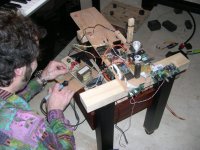
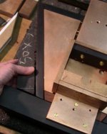
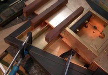
After 7 hours of work from 2 guys..the trannies were in place...that is inside the PiTbull Powersupply box
Tonight some serious listening to determine what the changes are...mind you everything is still wired in an experimental stage because the thing will be finished "by ear"
The Tent psu will be replaced cause it is not sufficient to supply the AT & T...fortunately there is just enough space to fill it with a homemade...
Here you see my friend Anton doing the hard work...while I am making tea.....😀
Attachments
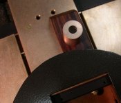
since there was no answer on my question few posts before this one, i have decided to go with the left suggestion.... using two bussbars, one next to the other and the third one on top of them and on that third one i will put my mechanism..... it will be bolted using brass spacers .... hopefully it will sound good....
also arround this construction i will put some wood... will see about that later.....
also arround this construction i will put some wood... will see about that later.....
I have seriously thought about your question but I reckon it is very hard if not imposible to aswer......
Even Peter is switching from springs to hard suspension...no minor detail in a design like this (or actually ANY design) but I take it that his idea comes through listening.....and comparing....done in your own set-up......those are/should be your ONLY parameters with this contraption.
Another way of building it.... is as a direct copy... in trusting the designer and its philosophy....but that stays a risky game.......
I personnally would definitely build it in a way that I can change it and compare it...to the previous tweak
(your mechanical set-up)...that should turn out very fruitfull...😉
thnx Erik - much appreciated.....
yes - i agree... there is no oher way ... i can see that now.... i will build the first suggestion and start working from that point on the mechanism...... ;D
we will se where i will end up.....
yes - i agree... there is no oher way ... i can see that now.... i will build the first suggestion and start working from that point on the mechanism...... ;D
we will se where i will end up.....
Erik - in post 1329 of this thread.... you have played with some brass (you say copper - so i do not know if they are copper or brass) standoffs.....
i have found the same looking material and would be happy to know how were you satisfied with those standoffs...... i would use only two of them.....
if you can remember - of course.....
thnx....
also - do you still use those small weights for the action - post 1514 of the thread.....
i have found the same looking material and would be happy to know how were you satisfied with those standoffs...... i would use only two of them.....
if you can remember - of course.....
thnx....
also - do you still use those small weights for the action - post 1514 of the thread.....
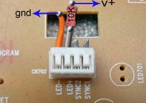
I connected the 10k resistor to the orange wire and the other wire connect to ground. I cant the see the LED back light. is it the LED drops off ?
its because you reversed the polarity of the voltage for the LED....
orange wire goes to the positive rail and grey one to the ground.... in between you have resistor in series with the LED....
orange wire goes to the positive rail and grey one to the ground.... in between you have resistor in series with the LED....
does anyone have a complete measurement of the upper pllate of the mechanism - where the laser is and where the holes are and everything...... i know Erik did some measurement and probably Peter also - but does anyone has it in some file or a picture.... so that i do not have to measure it all again.....
PLEASE !!!
!!!
PLEASE
!!!ccshua:
I think you connected the LED the wrong way around. The orange wire goes to ground, the grey wire should have the resistor in series and then connected to the + rail. Check the markings on the board, I think you will see the orange wire is labelled LED- and the grey next to it as LED+
Fran
I think you connected the LED the wrong way around. The orange wire goes to ground, the grey wire should have the resistor in series and then connected to the + rail. Check the markings on the board, I think you will see the orange wire is labelled LED- and the grey next to it as LED+
Fran
woodturner-fran said:ccshua:
I think you connected the LED the wrong way around. The orange wire goes to ground, the grey wire should have the resistor in series and then connected to the + rail. Check the markings on the board, I think you will see the orange wire is labelled LED- and the grey next to it as LED+
Fran
oupss.... you are right - my bad.... i saw the polarity wrong way.... the led - correct.... my bad
😀 sorry ccschua
audio1st said:
right - 😀 thats the thing i wanted to say... but - because i am writing in paralel on two forums and also working on my pc and arguing with my son (in a positive way - he is 5 months old) - it is a problem to do everything right - ahahahahah 😀
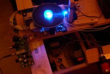
Erik - inspired by your blue LED i will also put some blue LEDs to have some light while changing CD's.... these last days i was going almost nut's while trying to change some cd's and not to disturb the laser .... it is very close to the disk.....
so there shall be some light afterall ;D
😀
so there shall be some light afterall ;D
😀
- Home
- Source & Line
- Digital Source
- Finally, an affordable CD Transport: the Shigaclone story