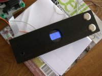
I finished the display...
For those among you who are NOT superstitious
...one of the two expensive switches was internally defect while I was looking elsewhere....yesterday the extended infra red eye
worked perfectly...today nothing...and while everything was assembled I saw a tiny white dustparticle underneath the very first transparant foil-layer of the display...so the whole show dismantled again...grrrrrrrrr
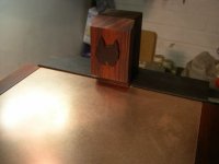
Anyway it is completed...and bravely showing no. 13
For those among you who are NOT superstitious
...one of the two expensive switches was internally defect while I was looking elsewhere....yesterday the extended infra red eye
worked perfectly...today nothing...and while everything was assembled I saw a tiny white dustparticle underneath the very first transparant foil-layer of the display...so the whole show dismantled again...grrrrrrrrr
Anyway it is completed...and bravely showing no. 13
Attachments


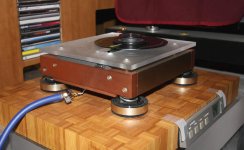
okapi said:tripmaster,
very tight.
how does it sound?
Tim
Thanks Okapi
It sounds much better than it looks 😉
Puffin said:Well Trippy, What a stunner. Looks a million dollars, but sounds s*ite right 😀
Is that a cardboard case ?
No...Bakelite, cant you tell? 😀
okapi said:
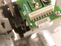
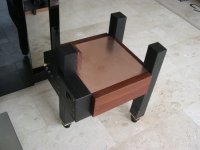
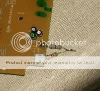
can you take a pic or describe where this solder bridge is located?
In the picture it's the solder blob at the lower left end of the board, near the left hand end of the ribbon connector. Removing it with desoldering braid will reveal two separate islands.
John
Attachments
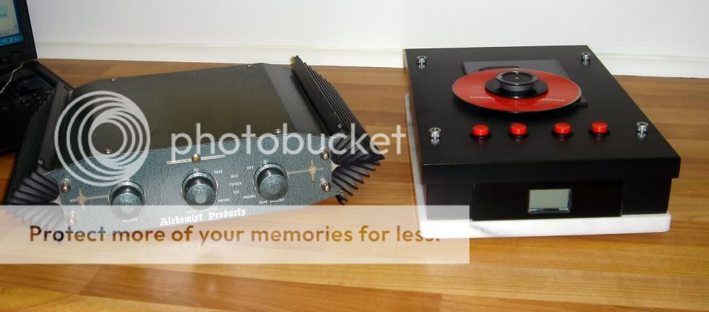
Erik van Voorst said:Hi Tripmaster..if you own the amp in your avatar the transport will match beautifully 😎
Hi Erik
Arrrgh.....I should have painted it with hammerite!
All I need now is some green buttons and a green CD 😉
Richard

jonners said:
In the picture it's the solder blob at the lower left end of the board, near the left hand end of the ribbon connector. Removing it with desoldering braid will reveal two separate islands.
John
thanks for the reply. i thought mine was non functional.
Hi all,
I'm about to go make a cable for the SPDIF output from the shigaclone to the DAC. Both will have BNC conectors. I have good quality 75R coax with copper foil and sheath, single conductor core.
So what length should I make this cable. I've seen arguments for the shortest possible path (in my case c. 6") and also for much much longer - in fact 16' was recommended.😕
So what do you guys think? I'm no expert at any of this, so can't produce any arguments for or against, but I know many here will know what to do!😀
Help!!
Fran
Shiga into Peters DAC sounds great BTW so far!
Contrary to what has been claimed for analog interconnects, with digital it seems that longer lengths are actually better, some explanation can be found here: http://www.diyaudio.com/forums/showthread.php?postid=1474680#post1474680
Based on my personal listenings experiments, I didn't like much 12ft or longer cables. However, there is a definite improvement when comparing 3ft to 6ft (with Belkin Synapse): with longer cable there is more dimensionality and separation, at least that was my impression.
You may consider attaching one end of the cable directly to transport's output, therecommended resistor divider is 300R (series) and 100R (shunt, directly across the output)
Attachments
Hi
Has anyone tried installing a Kwak Clock in to the Shigaclone, if so did you experience any improvement?
Richard
Has anyone tried installing a Kwak Clock in to the Shigaclone, if so did you experience any improvement?
Richard
Thanks Peter,
Its very appealing to make it short as possible - it just removes the clutter and bag of snakes that is the back of my audio rack. What I think I'll do is make it 7' long - hey 7 is a lucky number!!
I could go direct to the transport, but its really handy being able to disconnect it with ease. I know, I know..... but I will use BNC connectors both ends and hopefully reduce losses as much as possible. I'm using some riken 300R/91R for the output from the shigaclone.
I don't have a good understanding of all this impdeance stuff - I'm gonna start a new thread for this and measuring SPDIF.... I've searched and googled but short of spending hours sifting, an answer from the gurus here is best route.
Fran
pics to come tomorrow.....
There was some discussion about it here: http://www.diyaudio.com/forums/showthread.php?postid=1482732#post1482732
My understanding is that the source's resistance plus series resistance in parallel with shunt resistance should be producing 75R and such resistive devider provide required voltage attenuation.
My understanding is that the source's resistance plus series resistance in parallel with shunt resistance should be producing 75R and such resistive devider provide required voltage attenuation.
I think I posted this some time ago, but can't seem to find it.
Very helpful in describing why cable length matters.
http://www.positive-feedback.com/Issue14/spdif.htm
Very helpful in describing why cable length matters.
http://www.positive-feedback.com/Issue14/spdif.htm
Thanks to all, that positive feedback/empirical audio article is helpful indeed. He very much seems to advocate using 1.5m but not even numbers of metre lengths. So don't use 1 or 2 or 4. Seems if I use 8' that would be 2.43m long. I think thats what I'll go for. I'll do it and report back here.
Fran
Fran

I have a daft question...
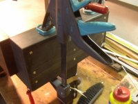
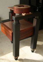
I have dismantled my Shigaclone again and have decided to attached a BNC socket to the rear of the drive.
Peter provided the following picture and I just wanted to check something with you.
As you can see there is a 300ohm resistor attached to the dig-out and a 100ohm connected to the TOC switch ground. Do I attach the core of the coax to these resistors? It seems strange that ground and signal are connected together.
Thanks
Richard
- Home
- Source & Line
- Digital Source
- Finally, an affordable CD Transport: the Shigaclone story