OK, so I went back to basics. Based on the pic of the transformer with the order of blue-green-blue-green. Lets call them 1-2-3-4. I measured the following with the DMM on continuity mode:
1-2 = continuity, hence sec.#1
1-3 = no continuity
2-3 = no continuity (Vunce, is this what you meant by no continuity)?
3-4 = continuity, hence sec#2
Should be OK so far, so I hooked up as follows: 1- (2 & 3 joined) - 4 and checked continuity as follows:
1-4 = continuity
1-2&3 = continuity
2&3 = continuity
4-2&3 = continuity
So based on the above I think everything OK electrically and I can proceed, or am I that daft ?
Thanks for the help,
MM
OK, so I went back to basics. Based on the pic of the transformer with the order of blue-green-blue-green. Lets call them 1-2-3-4. I measured the following with the DMM on continuity mode:
1-2 = continuity, hence sec.#1
1-3 = no continuity
2-3 = no continuity (Vunce, is this what you meant by no continuity)?
3-4 = continuity, hence sec#2
Should be OK so far....
Yup, sounds like your on the right path")
If you haven’t decided on placement in your case and on the heatsink - I would do that as the next step.
Do it as if final, with all the board spacers and connectors as close to final position - the worst is drill and tap your heatsink to find you were 1/2” too low and the board is in the way after you put the spacers on.
IMO if you are drilling and tapping your heatsink, I would just solder the mosfets to the board, but everyone has their preference.
Myles,
If you’re using flying leads for your MOSFETs disregard what I’m going to recommend.
If you’re soldering the MOSFETs to your PCB board, don’t do it until you have the pcb mounted to the heatsink on stand-offs, put the thermal pads in place, the MOSFETs on top of the insulators with the legs loosely through the PCB. Mark on the heatsink the holes needed for the Mosfets. Remove the pcb’s, drill and tap the holes. Put everything back on the heatsinks, screw down the mosfets,(fender washer and split washer with M3 screw) now solder the legs. I find this way removes any stress from the mosfet legs because they are exactly in the position they need to be in before they are soldered. I know, It’s a few extra steps
Also, try placing both psu boards to the front of the chassis across from each other and the amp boards at rear of the chassis. I think you’ll find wiring up all the boards will work better in this configuration rather than crossing diagonally from each other.
Last edited:
bullittstang and Vunce,
Thanks for the building advice. I will absolutely layout the transformers, psu's, amp;s and SSR's to make sure it is done correctly. Will be soldering the leads onto the snubber boards and then attaching the other ends to a male molex connecter to attach to the female box installed on the pcb.
Some questions I will ask are:
How high is a normal spacer, 1/4", 1/2", or more?.
What are they usually made from, brass or stainless steel ?
Are the washers between the pcb and spacer nylon or metal?
I have an hardware order going in to mouser, so thought I would pick up a bunch of the above.
Thanks again
MM
I use this type for mounting pcb’s to the heatsinks:
https://www.amazon.com/dp/B073XP7MZ6/ref=cm_sw_r_cp_awdb_imm_XS6EG73VK5KNFFPBXBVR
This type for all other pcb chassis mounting:
https://www.amazon.com/dp/B083GM48C1/ref=cm_sw_r_cp_awdb_imm_F0XXX3QN3S1M9E3KEAV2
No washers,
Nylon spacers not needed if pcb mounting holes are electrically isolated.
It doesn’t hurt to have some on hand just in case of those non-isolated situations.
Beware: TO-247 and TO-3P have LOTS AND LOTS of lead length and can easily accommodate a PCB which floats in the air, 10mm above the mounting plane of the device's heat spreader plate. But TO-220 ... not so much! Carefully work out the arithmetic, or mock-up a hardware experimental test vehicle, and double triple check that the leads are solder-able to the board 10mm above. I bet they aren't.
Mfets
Hi,
Getting my Mfets wired up and looked at a lot of pics to see if I got it right. In the pic attached, White is the gate, blue is the drain, and red is the source. When they go in the moles box, I have the gate and the source on the top row and the drain on the bottom row on the right side. Is this correct?, would hate to make an error.
Also, If it is correct, does it matter which side of the box the drain is on?
MM

Hi,
Getting my Mfets wired up and looked at a lot of pics to see if I got it right. In the pic attached, White is the gate, blue is the drain, and red is the source. When they go in the moles box, I have the gate and the source on the top row and the drain on the bottom row on the right side. Is this correct?, would hate to make an error
.Also, If it is correct, does it matter which side of the box the drain is on?
MM
I am going dual mono and I am planning wire up 2 Xfmrs to 1 IEC power module. I am wiring like this:
I have the primary leads from the Xfrmrs in parallel to one side of a double row 4 pole terminal block. So 2 red wires per pole and 2 black wires per pole.
I would then have a wire from each pole on the other side of the terminal wired together. So 2 reds joined and 2 blacks joined. These would then attach to the IEC module or to a double row 2 pole connector, so as to have only one single wire going to the live and neutral of the IEC module.
Is this good and common practice? Thanks for the help.
MM

I think what you have is correct Myles but your diagram showing the terminal blocks is confusing. What we need is an interconnect diagram. How you connect them (terminal blocks, wire nuts, Wago connectors, P2P solder, doesn’t matter. A diagram similar to this would be really helpful. This is not dual mono but you get the idea:
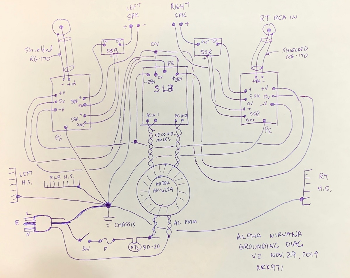
Here is a dual mono with SLB. In your case the All Cee’s PSU connects two secondaries together for a “center tapped” configuration. This uses 1 full wave bridge vs two when doing independent secondaries.
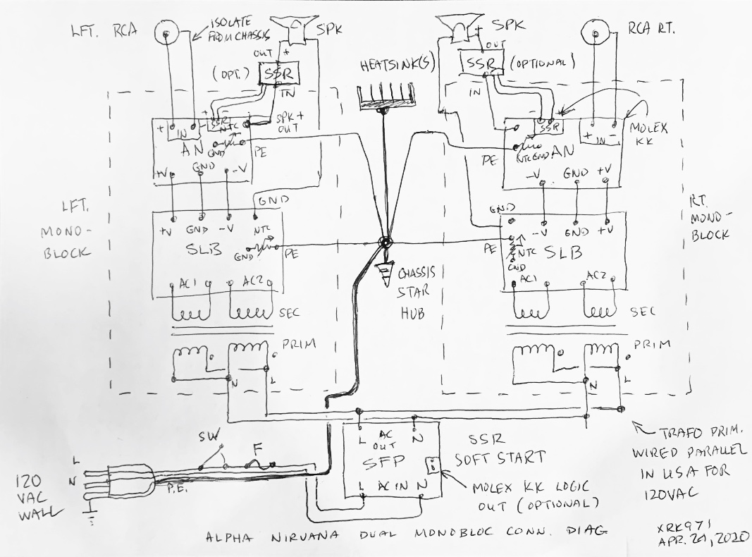
Here is a dual mono with SLB. In your case the All Cee’s PSU connects two secondaries together for a “center tapped” configuration. This uses 1 full wave bridge vs two when doing independent secondaries.
Thanks X, the diagrams are very helpful and will be more helpful as I progress with the builds. For now, I wanted to know how most builders connect their parallel primaries back to the IEC socket, since dual mono there is 2 pairs of neutral and 2 pairs of live to contend with).
On my diagram, I show 2 pairs of Red neutral wires and 2 pairs of Black live wires from the 2 transformers connected to a 4 pole terminal block. My terminal blocks are continuous from one side to the other. These wires are then reduced to 2 red neutral wires and 2 black live wires that are twisted together and attached to the next terminal block. Then finally the single red neutral wire and black live wire are fastened to the IEC module. My IEC module has the mains inlet, a fuse and rocker switch in one module. I need to wire a NTC 8D-20 if needed.
I read that coming out of the IEC module there should be only a ground wire, a neutral wire, and the live wire. The wires that are twisted together are terminated at terminal blocks, not at the IEC.
Anyways, I think I have this part correct, and I thank you for time and patience.
Myles

- Home
- Group Buys
- FH9HVX - Budget Conscious 100w Class AB for Lean Times