This post outlines how to calibrate the bias properly: https://www.diyaudio.com/forums/gro...-100w-class-ab-lean-times-69.html#post6524085
I also made the mistake of plugging in the AC to the rectifier and using that as a power supply the first time around, once I reworked the board I used my DP832 to provide +/-30V rails, capped at 100mA to know if anything was off and used that to bring the bias into the correct range.
I also made the mistake of plugging in the AC to the rectifier and using that as a power supply the first time around, once I reworked the board I used my DP832 to provide +/-30V rails, capped at 100mA to know if anything was off and used that to bring the bias into the correct range.
Hi all,
Quick question about construction. Which component should be after the AC power module, the EMI reducer or the soft start module ?
Regards,
MM
Quick question about construction. Which component should be after the AC power module, the EMI reducer or the soft start module ?
Regards,
MM
Thanks Mark for the link. I never even knew that they were available. I have some Fo-Felix boards on hand that I will use for the next few projects.
MM
MM
Schurter is top of the line (precision German made?). Snap in ones are finicky to fit right unless you have access to a metal shop. Schurter also makes screw mounted ones may be easier format for IEC power entry modules with switch fuse and filter. Note that Schurter sells the required “fuse drawer” for an additional $6 so they are kind of pricey for a budget amp build.
Not as high quality, but serviceable are Chinese made AliExpress ones like this:
10A power EMI filter with big rocker switch & socket Connector CW2B 10A T(003)|Connectors| - AliExpress
If you have an internal switch you can save a little:
IEC inlet module AC power socket with fuse EMI filter 6A 115V/250V 50HZ/60HZ|Electrical Sockets| - AliExpress
If you skip the filter, it’s like peanuts:
1set 10A 250V Inlet Module Plug Rocker Switch Male Power Socket 3 Pin IEC320 C14 switch + Fuse New|pin switch|pin pinpin 1 - AliExpress
Hi X,
For the little turn off module for the Gen1 SSR, would I insert it on the output of the All C's PSU?. Alittle confused, so needed to ask.
Thanks,
Myles
For the little turn off module for the Gen1 SSR, would I insert it on the output of the All C's PSU?. Alittle confused, so needed to ask.
Thanks,
Myles
You mean the “instant off” mod?
Ready-to-Run (RTR) SSR DC Speaker Protection and Delay GB
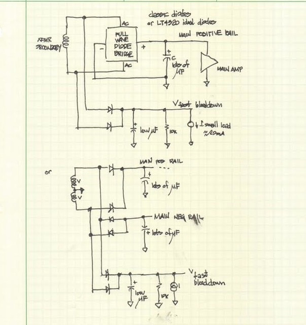
It’s a very low capacitance half wave rectified power supply connected to the secondaries of the transformer. That is the input of the All Cee’s before the rectifier. It serves to make rectified power to barely power the SSR protection circuit. When power is switched off, it loses power in about 150 milliseconds and the SSR shuts off before the amp can make a pop or thump on your speaker.
It will work with the Gen 2 SSRs also. Costs maybe $2 to make.
Ready-to-Run (RTR) SSR DC Speaker Protection and Delay GB
It’s a very low capacitance half wave rectified power supply connected to the secondaries of the transformer. That is the input of the All Cee’s before the rectifier. It serves to make rectified power to barely power the SSR protection circuit. When power is switched off, it loses power in about 150 milliseconds and the SSR shuts off before the amp can make a pop or thump on your speaker.
It will work with the Gen 2 SSRs also. Costs maybe $2 to make.
Thanks X, so I can either solder a wire onto the + and - secondaries to access the All C's and the Instant off, or use a single to double output block for each + and - secondary. Hope I am not confusing you.
MM
MM
The secondaries are AC, so no +/- other than phase markers to align use of two secondaries in parallel or series.
Basically, you are making your own very very small all Cee’s PSU with only a half wave bridge and a 22uF cap.
Basically, you are making your own very very small all Cee’s PSU with only a half wave bridge and a 22uF cap.
Thanks X, will give it a try. If building dual mono and using 1 of these per channel, only one 10K bleeder and one output to the SSR per board is needed, Correct?
Thanks
Thanks
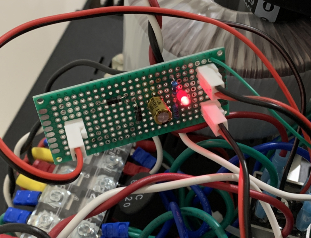
Yes. You can add an LED in series with the 10k resistor for a nice indicator. I actually used only one on one transformer and shared the output to the two SSRs. This did not cause a ground loop or hum because the gates for the SSRs are connected via an optical isolator.

Please move LED in series with 10k (cathode (flat) towards ground) or it will blow up. Otherwise, looks good.
X, is it because the arrows on the led are pointing upwards, that I gave the impression that the cathode is pointing towards the non ground rail. I always install cathode (shorter lead) to the ground or- rail.
I honestly thought the arrows just meant "light emitting". Or am I completely out to lunch.
MM
I honestly thought the arrows just meant "light emitting". Or am I completely out to lunch.
MM
Yes arrows mean emits light. Or LED. But symbol is still diode. I think you have a circle - which I am not sure is anything but maybe a gas discharge tube. 🙂
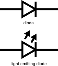
X, sorry about my symbol for the diode. If I install the circle (really an led) on my diagram with the cathode to ground everything should be good, Correct?
MM
MM
Yes. But put it in series with the resistor. If cannot be used by itself - too much current and it will blow up.
- Home
- Group Buys
- FH9HVX - Budget Conscious 100w Class AB for Lean Times