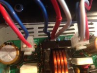
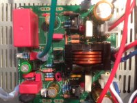
Vunce,
Mfets and send a pic
Both V+, V- are 47.8 around the 110 V AC range, so good news.
X, I will check Mfets and send a pic.
MM
Mfets and send a pic
Both V+, V- are 47.8 around the 110 V AC range, so good news.
X, I will check Mfets and send a pic.
MM
That looks correct for the MOSFETs. Have you checked the acne multiplier connections?
Also, do you have the N channel and P channel correct?
Also, do you have the N channel and P channel correct?
Hi x,
Not sure what you mean by:
1. Have you checked the acne multiplier connections? (Not sure what this means)
2. Do you have the N channel and P channel correct? ( Have we not confirmed this, I have an IRFP240 -N channel, and IRFP9240 for the P channel, connected as per the pics, GDS (White Blue Red ) on the heatsink, and hopefully connected to the Molex box correctly.
Thanks for the help,
MM
__________________
LOL, iphone auto spell in action for you there. 🙂
I meant have you checked Vbe multiplier connections. (The BD139 BJT temp sensor).
Have you checked the acne multiplier connections?
I meant have you checked Vbe multiplier connections. (The BD139 BJT temp sensor).
X,
BD139 is a 123, emitter, collector, base. On my heatsink it is white, red, blue.
On the amp board I soldered white, red, blue starting from the left, by the trimpot screw.
Have I got it correct?
MM
BD139 is a 123, emitter, collector, base. On my heatsink it is white, red, blue.
On the amp board I soldered white, red, blue starting from the left, by the trimpot screw.
Have I got it correct?
MM
Edit: looking at your photos it shows V123 connected at the PCB left to right blue red white, corresponding to ECB. On the Bd139 mounted on top of the MOSFET you have White Red Blue. Or backwards. Try swapping white and blue wires on V123. That would definitely cause amp to not work.
Please take some closeup photos of the amp boards so we can make out details like resistors etc.
What is the voltage of the speaker output when you turn it on at low voltage with Variac in place?
Please take some closeup photos of the amp boards so we can make out details like resistors etc.
What is the voltage of the speaker output when you turn it on at low voltage with Variac in place?
Last edited:
Hi X,
After looking at the schematic, I do believe you are right. I have the emitter and base in the wrong positions. I will have to undo the amp board from the chassis as things are to tight to wield my solder iron. Will report back once I am done.
After looking at the schematic, I do believe you are right. I have the emitter and base in the wrong positions. I will have to undo the amp board from the chassis as things are to tight to wield my solder iron. Will report back once I am done.
Hi Myles,
Your Vbe multiplier (temp sensor) connections look good now. For a first test - no load is needed to be connected. What we want to see is that the amp flows bias current from the +ve rail to the -ve rail through the two source resistors in a way that is stable and controllable. When you first turn it on, monitor the voltage across the 0.22R 5W power resistors. We are looking for about 120mA - so 0.12A x 0.22ohm is about 26mV. If you get single digit volts, that is way too high. If on a variac, adjust the the bias current setpoint pot to bring it down to 26mV, and if it doesn't respond or is unstable, remove power and investigate.
For a dummy load resistor - use at least a 10w 8ohm or 10ohm resistor connected from out to GND. The usual white cement filled crossover resistors can work. Note that this amp can put out 100w, so it can easily smoke a 10w resistor if full power is applied.
But you can check for proper amp startup without a resistor on the output. Check the output voltage to make sure it is close to 0v. Anything about 100mV and above is a problem that needs to be fixed. It should be close to 5mV to 10mV typically.
Good luck! I predict that it wil work fine now - your problem was a miswired Vbe multiplier connection.
Thanks X,
Do I have to test both bias points, or just one set per board. ?
Also, I connect the GND on amp board to the Black wire of DMM and the Out to the red wire of DMM. Measure DCV.?
MM
Do I have to test both bias points, or just one set per board. ?
Also, I connect the GND on amp board to the Black wire of DMM and the Out to the red wire of DMM. Measure DCV.?
MM
Hi Myles,
Only one set of test points between either resistor is fine. Yes, red probe to Output and black to GND on amp.
Only one set of test points between either resistor is fine. Yes, red probe to Output and black to GND on amp.
X,
Connected bias points and put about 3VAC on the variac. The DMM measured 21mV. Took it up a bit higher just to see if the voltage increased, it did. So I shut it down. The trim pot had no effect on the bias voltage.
Also the output voltage was 2.5V
i looked at your testing pics and the only wire you have that I do not is the double green wire whose end point is hidden by the big Wima cap.
What to check next?
MM
Hi Myles,
Sorry it’s so difficult. Is the LED lighting up? 3v is not enough to get the amp to properly work. It needs at least 24v for the setpoints to work.
Sorry it’s so difficult. Is the LED lighting up? 3v is not enough to get the amp to properly work. It needs at least 24v for the setpoints to work.
Hi X,
No need to be sorry, this is how we learn. The LED on neither the PS or the amp board lights up.
I tried the other channel and I was able to power up to full voltage (no smoke). PS LED's came on, Amp board LED - no light. Had 0.2 mv bias and 19 V on the output. No variation in bias voltage from turning trimpot screw.
MM
It sounds like you have the amp LED backwards. The cathode (flat) faces away from the ground pin.
Hi X,
Thanks for the info. I am trying to get enough light and magnification to see if I can determine the cathode orientation. So, the cathode (flat part) faces away from the 0V pin. If I look on the bottom side of the pcb, I see that their is a trace from the LED to the nearest resistor. I assume the cathode follows this trace to the resistor. Correct?
I may have to remove the LED to make sure of the orientation. Such is diy.
Thanks,
MM
Yes, cathode faces resistors. You can look at the schematic and see that. Without that LED current, there is voltage in the VAS stage and no current flowing on the outputs.
My solution for utter and complete beginners: specify a 2-pin, bidirectional LED in the Detailed Parts List. Now it is impossible to insert the LED "wrong". In either orientation, the LED is guaranteed to light up. Most 2-pin, bidirectional LEDs are also two color; so, it glows color-1 when inserted in orientation-1, and it glows color-2 when inserted in orientation-2. But it never goes black, it always glows.
examples @ Mouser
examples @ DigiKey
The Noir headphone amplifier in the Store uses this little stunt, and first time builders are pleased by it.
examples @ Mouser
examples @ DigiKey
The Noir headphone amplifier in the Store uses this little stunt, and first time builders are pleased by it.
- Home
- Group Buys
- FH9HVX - Budget Conscious 100w Class AB for Lean Times


