X,
Light bulb went on. Attach the anode of led to the bottom resistor lead and the cathode of led to the ground rail, then it is in series. Correct. Wow if correct, I will never forget.
Light bulb went on. Attach the anode of led to the bottom resistor lead and the cathode of led to the ground rail, then it is in series. Correct. Wow if correct, I will never forget.
FH9 wiring
Hi X,
I have begun sorting some wiring. In the pic attached, I have connected the primaries in parallel (paired the blacks, paired the reds). When I connect to the SFP, can I just connect 1 wire to both the PRI 1 115 (J4) and the PRI 2 115 (J8) or do I have to have wires to J7 & J3 also. Thanks for the help
MM
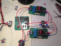

Hi Myles,
I don’t know what you are connecting there in the photo? Are those CMC line filters? If so, you only need one, no need to parallel it.
Here is how it works: from wall plug - IEC inlet plus switch - CMC filter - SFP - trafo primaries.
How you wire the primaries depends on your local mains. I assume Canada is 120vac 60Hz?
Then on Antek trafo parallel the primaries red and black and connect those to the output of the SFP. There are extra connections there for connecting two trafo in parallel or series depending on your local mains. Please post question about SFP in SFP thread. Use the schematic in that thread.
If you need an overall connection diagram let me know.
X,
Will be installing MFets, and some ground connections. Do you still recommend a couple of series connected 10ohm 10W power resistors for each channel between the AllCees PS and FH9HVX amp board. Will be powering up with variac.
Also, I am not going to test into speakers, so do I also need some power resistors on the outputs of the amp board.
Thanks for the help, getting closer to power up.
MM
If you have variac then no need for safety power resistors. You can use 10w 10ohm safety resistor as test load.
Hello All,
I am ready to power up my FH9HVX build (I think). I am attaching 2 images of the build. The 1st image shows the IEC plug which will be attached to a Variac. It shows the SFP and the Fo-Felix EMI filters for each transformer, and a glimpse of the ground terminal between the 2 transformers.
The 2nd image shows the ground terminal and the wiring from transformers to the AllCees and then the amplifier. All grounds are brought back to the ground terminal, which is attached to the base of the chassis.
If some of you builders with more knowledge than me can have a look at this and let me know any glaring errors, It would be appreciated.
I have my DMM hooked up to the test points, and another DMM connected to a 10ohm 10W resistor which is connected to the Out and GND terminals on the amp board.
After testing I will build the enclosure and hook up all the inputs and outputs. I first just want to see if it works or produces magic smoke.
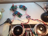
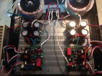
Thanks, I apologize for the pic quality of my phone.
Myles
I am ready to power up my FH9HVX build (I think). I am attaching 2 images of the build. The 1st image shows the IEC plug which will be attached to a Variac. It shows the SFP and the Fo-Felix EMI filters for each transformer, and a glimpse of the ground terminal between the 2 transformers.
The 2nd image shows the ground terminal and the wiring from transformers to the AllCees and then the amplifier. All grounds are brought back to the ground terminal, which is attached to the base of the chassis.
If some of you builders with more knowledge than me can have a look at this and let me know any glaring errors, It would be appreciated.
I have my DMM hooked up to the test points, and another DMM connected to a 10ohm 10W resistor which is connected to the Out and GND terminals on the amp board.
After testing I will build the enclosure and hook up all the inputs and outputs. I first just want to see if it works or produces magic smoke.


Thanks, I apologize for the pic quality of my phone.
Myles
Nice work. Myles!
Let her rip!
If you have a variac - no issues should arise that can’t be caught early. Look at the DC offset at the output. That should be close to 0v. Typically under 50mV offset.
Good luck!

Let her rip!
If you have a variac - no issues should arise that can’t be caught early. Look at the DC offset at the output. That should be close to 0v. Typically under 50mV offset.
Good luck!

Hi X,
Thanks for the comment. I just thought of some thing: " Should I disconnect one channel while testing the other "? or make up another 10ohm 10W resistor for that channel.
MM
Thanks for the comment. I just thought of some thing: " Should I disconnect one channel while testing the other "? or make up another 10ohm 10W resistor for that channel.
MM
So, I powered up one channel, and nothing happened, no magic smoke, no offset, nothing.
LED's on all boards did not illuminate. I tried some things, but could not get any response from the boards.
I started with the basics, I checked my Variac, OK. I checked the voltage at the end of the IEC power cord, OK. I checked the fuse in the power entry module, OK. I checked the voltage on the output of the power entry module, it was 1-2 volts. This had me wondering?
I changed power entry module, same type, and powered up again, same result????
I then by passed the module and checked the voltage from the variac > power cord > SFP board. I have full voltage to the inlet of the SFP and at the Primary outputs 1 & 2 on the SFP board. The LED does still does not light up on the SFP board.??
I have attached a top pic of the SFP and btm pic of SFP for consideration. Any help is appreciated, the SFP was an easy build, maybe I forgot something. I am pretty sure the LED was oriented properly😕
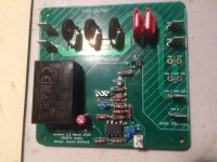
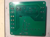
Thanks,
Myles
LED's on all boards did not illuminate. I tried some things, but could not get any response from the boards.
I started with the basics, I checked my Variac, OK. I checked the voltage at the end of the IEC power cord, OK. I checked the fuse in the power entry module, OK. I checked the voltage on the output of the power entry module, it was 1-2 volts. This had me wondering?
I changed power entry module, same type, and powered up again, same result????
I then by passed the module and checked the voltage from the variac > power cord > SFP board. I have full voltage to the inlet of the SFP and at the Primary outputs 1 & 2 on the SFP board. The LED does still does not light up on the SFP board.??
I have attached a top pic of the SFP and btm pic of SFP for consideration. Any help is appreciated, the SFP was an easy build, maybe I forgot something. I am pretty sure the LED was oriented properly😕


Thanks,
Myles
The SFP expects 120vac in order to make 5v required for the logic circuit to turn on. If the variac is giving less than maybe 80v it won’t turn on.
First just plug the SFP straight into the IEC outlet no variac and see if LED lights. If it does you need to skip the SFP for startup testing. It’s ok - just leave it out until you verify amps are set up properly.
First just plug the SFP straight into the IEC outlet no variac and see if LED lights. If it does you need to skip the SFP for startup testing. It’s ok - just leave it out until you verify amps are set up properly.
Hi X,
Powered up SPF to 120-130V, no LED response. Left it out of circuit along with the EMI filters and powered up to about 30 V AC, and R115 & R116 got smokin hot, so shut down. Might have to remove and have a look.
MM
Powered up SPF to 120-130V, no LED response. Left it out of circuit along with the EMI filters and powered up to about 30 V AC, and R115 & R116 got smokin hot, so shut down. Might have to remove and have a look.
MM
If R115/116 resistors of the All C's psu are smoking hot with only 30v ac input, sounds like you have a short somewhere. Does the psu board work without the amp board connected?
Hi Vunce,
So to confirm before I connect DMM to the PSU (after disconnecting from amp board). Connect V- from AllC's to black lead of DMM (com) and V+ to the red lead of DMM.
Also do I leave 0V connected from PSU to amp board.? DMM set on DCV.
MM
So to confirm before I connect DMM to the PSU (after disconnecting from amp board). Connect V- from AllC's to black lead of DMM (com) and V+ to the red lead of DMM.
Also do I leave 0V connected from PSU to amp board.? DMM set on DCV.
MM
Totally disconnect the amp board. On the AllC’s output, connect black probe to 0V, red probe to V+, that’s the positive voltage rail. Then move red probe to V-, that’s the negative voltage rail. Those +/- voltages should be equal or very close to it.
Hi Myles,
Also do a continuity check to make sure you don’t have a short between the mosfet drain (tab) and heatsink ground.
Check to make sure P and N channel are in correct locations and not swapped.
Check MOSFET wires for correct positions. GDS should go to correct pins on PCB.
Good luck!
Campfire and DIY sounds too good to be true! 🙂
- Home
- Group Buys
- FH9HVX - Budget Conscious 100w Class AB for Lean Times