Looks great Myles. Like Vunce said, move SSRs closer to the back where amp binding posts are located.
Thanks guys,
Good idea to move SSR to the rear panel. I need a bit of room down the center to run the power wires from the IEC module to the transformers (is this a good idea or is it better to route them across and down one side ? ).
Almost have the amp boards for the Xmas amp built. Waiting on a few parts. Lots of fun!
MM
Looks like gathering parts is becoming increasingly difficult with various shortages.
The Fqa36 mosfets are out of stock on mouser. I think I can get them on Avnet but have never bought from this company before. Does anyone have another source or substitution? I have a lot Fqa9n25’s on hand but their parameters don’t look close enough to the 36’s.
Also, the Koa Speer 5W resistors are out of stock. Is there a substitute for these? Maybe a 5W wirewound like the Vishal/Draloric?
You can use the the common IRFP240/9240 just fine. They may have a shorter lifespan than the Fairchilds which are rated for higher dissipation.
The KOA BPR are bulk metal non inductive resistors. They will have less distortion than wire wound resistors. Feel free to use Panasonic ERX 3W as a substitute. Those are thin film vs wire wound which is inductive.
The KOA BPR are bulk metal non inductive resistors. They will have less distortion than wire wound resistors. Feel free to use Panasonic ERX 3W as a substitute. Those are thin film vs wire wound which is inductive.
Thanks X. I should have remembered the irfp’s shown in the first schematic. It really pays to re-read post #1. Thank you for always summing up everything so well in those posts, X.
Thanks Zman. I ordered Some of each from Newark. Hopefully they get here soon.
Thanks Zman. I ordered Some of each from Newark. Hopefully they get here soon.
jwjarch, good to know that you were able to order the parts.
Keep us posted on your build updates. 🙂
Keep us posted on your build updates. 🙂
I am starting to bolt down some of my boards, and I have a question. Is there nylon washers underneath the chassis base or just a metal washer and nut attached to the pcb bolt. Thanks for the help.
MM
MM
Just chassis to brass stand-off and PCB bolted to brass stand-off with metal screw. The bolt holes are electrically isolated from the PCB ground except for the Gen2 RTR SSR’s. For these, please use the included nylon stand-offs.
Thanks X, I thought so. Are the Gen1 RTR SSR boards electrically isolated or are they the same as Gen2 and need the washers. I assume a nylon washer between the pcb and the bolt and no other nylon washers needed. Correct?
MM
MM
Progress pics
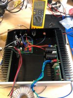
While waiting for some parts, here are some progress pics. Please comment if you see something weird. Full view, right and left channels. Sorry about my poor lighting.
X, I noticed that your PE connection on the amp board is doubled wired. Is one of the wires from some other component and you are joining there, before continuing to your ground block.


Regards,
MM
While waiting for some parts, here are some progress pics. Please comment if you see something weird. Full view, right and left channels. Sorry about my poor lighting.
X, I noticed that your PE connection on the amp board is doubled wired. Is one of the wires from some other component and you are joining there, before continuing to your ground block.
Regards,
MM
Thanks X, for my knowledge, can you briefly explain why decreasing the impedance of the PE ground wire is a good idea. Looking backwards, is it easier on the amp or the PSU.
MM
MM
In case there is a fault in the amp, you want as free of path back to mains earth ground to reduce electrical shock, fire, etc. Probably a single 16ga line is fine. I am just being extra careful. It also provides a lower impedance path for the RF filtering on the board to pass to earth ground (the 22nF cap between analog zero and PE).
Got a couple of hours to work on this again after a few weeks, got it hooked up and playing some initial music, sounds great and really full bodied. Appears that it struggles with really low volumes, as it'll clip the audio a lot until you give it a bit more amplitude. Any ideas as to what could be causing this? Possibly just the preamp?
Hi As8912,
Something is not right, it should not clip at low volumes. You might have a damaged active somewhere is my guess. You had smoke earlier? What caused that?
Photos and measurements of key voltages at all pins of all actives will let us help debug this.
Something is not right, it should not clip at low volumes. You might have a damaged active somewhere is my guess. You had smoke earlier? What caused that?
Awesome, thanks for the guidance everyone! The LED was the root of it, I swapped it in for a generic 3mm red LED with the correct polarity and it powered. Cautious of the bias voltage and runaway thermals, I only powered the amp on for 0.5 seconds at a time, initial bias voltages were ~180mV instantly, dialed it back a few times but all 0.22ohm resistors were fried (both on the amp, and both on the All Cees board), will order more resistors and mosfets. Anything else I should be aware of/get spares of before I cause real damage? (blown capacitor, etc)
Photos and measurements of key voltages at all pins of all actives will let us help debug this.
The issue then was the bias voltage was massively off, lead to thermal runaway of the mosfets and shorted the mosfet leads. I've replaced the 0.22ohm resistors on the FH9 and All Cees (they were all cracked), and both power mosfets on the FH9.
Datapoints:
Bias+ PD:
0mV start
peak 52mV 14 seconds
settles 24.8mV after ~90 seconds
settles 20.5mV after 20 minutes
Negative rail: 49.945V
Positive rail: 49.960V
V129
Emitter: 49.000V
Collector: -2.990V
Base: -38.340V
V124
Emitter: 48.920V
Collector: 4.74V
Base: 48.33V
Those were the two most accessible and looked like likely candidates from the schematic, is it worth probing all of the following; V121, V101, V103, V113?
Attachments
- Home
- Group Buys
- FH9HVX - Budget Conscious 100w Class AB for Lean Times