Thanks X,
I may have to put the PS's and amps across from each other as I have to wire the 2 transformers to one IEC inlet and then to the 2 PS's. It would be hard to do that with them being diagonal ( one secondary would have short wires and the other longer wires).
Unless an 8" difference in secondary wire length will not make a difference? Suggestions?
I guess I could leave them both long also?
MM
Zman01,
Thought it might look all right, just testing the waters. I am pretty sure I will be putting the transformers at the bottom of the pic, then the PS's, then the amp's, then the SSR's. Heat sinks will be more towards the mid to back to even out the weight of the Xformers at the front. Thinking out loud to see what others have built also. Lots of pics on the forum for ideas.
Thought it might look all right, just testing the waters. I am pretty sure I will be putting the transformers at the bottom of the pic, then the PS's, then the amp's, then the SSR's. Heat sinks will be more towards the mid to back to even out the weight of the Xformers at the front. Thinking out loud to see what others have built also. Lots of pics on the forum for ideas.
Fellow builders,
I would like to ask the following rather than burning up some transformers. I looked at post # 224 which shows X's griddle amp. I can see the primary winding are in parallel, but not sure about the dual secondaries
I have 2 x AN-3236 with dual primaries & dual secondaries for a dual mono FH9HVX. I would like to test the AC voltage of the transformers before attaching to the PS. I have wired the primaries in parallel.
Do I wire the secondaries in series or parallel ?
If wired in series, would one measure the voltage value between the two single wires.
Thanks for the newbie help.
Myles
Since you are using All Cee’s PSU you need to wire the secondaries in series. Connect the green of one secondary to the blue of the other. That common point is then connected to 0V input of the All Cee’s and the other two ends go to the AC input. Test the voltages on the output of the All Cee’s before connecting any load. Have your hand on the power switch (an outlet strip with switch is handy for this) ready to disconnect in case there is a problem. Stand back at least 6 ft and wear safety goggles upon first power up in case a capacitor blows up. Make sure they are installed with correct polarity. You should get about +/-51v output. If DMM connected to +/-output you will see 102v total.
Yes, good idea to take it step by step. If you wire the secondaries with incorrect phase, you will hear a heavy buzzing sound from the trafo as it’s a dead short. And fuse will blow (make sure you have a fuse). If a 4A fuse blows you need to find the source of the problem rather than change the fuse and try again.
Trans AC voltage test
I wired up the primaries in parallel & secondaries in series. I had the IEC power module grounded to a slab of Alu. I did not check the fuse in the power module as it said to use a 250V fuse, so I thought that is what would be in the power module. Started the variac and slowly brought the voltage up, while watching the +/- voltage on the DMM. Voltage on the DMM rose to about 50 volts and then dropped to zero.
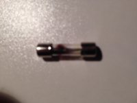
Shut everything down and checked the variac- it is operating OK. Checked the fuse and it looks like it was burnt (see pic). Fuse was 125V-6A. I checked my wiring, to see if everything was tight and wired correctly. Seemed OK. To be sure I cut off my soldered wire joints and twisted the wires together again and tightened back down in the terminal blocks.
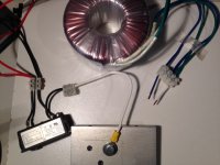
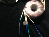
I do not have any 4A fuses on hand, so will have to wait to get to the store. Please see the photo's below to see my wiring (sorry about the shadows and poor lighting). Red-Red & Black-Black to power module. Blue, Blue-Green, Blue for secondaries.
All help appreciated,
MM


Was that a slo-blow or fast blo? You need a slo blow on the line to withstand in-rush currents.
I don’t see any issues with your wiring if done as you described.
You also don’t need to have the IEC ground connected just to test your xfrmr, it is for safety when you put in a case.
I don’t see any issues with your wiring if done as you described.
You also don’t need to have the IEC ground connected just to test your xfrmr, it is for safety when you put in a case.
Myles,
What is the AC mains voltage where you are located?
Antek trafo’s typically have blue/green secondary windings, so your blue, green-blue, green test setup seems fine. You can check an individual winding with your DMM in continuity mode. Power off, Probe on green wire, probe on blue wire (polarity doesn’t matter) the meter should buzz.
DMM beeps on continuity measuring single green - blue wires & joined blue-green wires. Was pretty careful powering up, but you never know. I will get some proper fuses and try again. Like I commented earlier, I have re-twisted and tightened up connections again. I think I will look for some terminal blocks for spade connectors or some more robust terminals for wire connections. Any suggestions will be welcome.
I went back and looked at your picture again, it’s hard to tell, but looks as if the blue/green wires tied together in the euro block are from the same secondary? If that’s the case you have a dead short.
Can you post a better picture of the secondaries wired in that block and the transformer so it will be easier to follow the wires?
Can you post a better picture of the secondaries wired in that block and the transformer so it will be easier to follow the wires?
- Home
- Group Buys
- FH9HVX - Budget Conscious 100w Class AB for Lean Times
