I thought the same thing, but if you look closely you can see the black wire going to the 0V faston just below the red Wima film cap 😉
V132 P Channel:
Gate: 0.001V
Drain: -50V
Source: 0.118V
V131 N Channel:
Gate: 0.001V
Drain: 50V
Source: 0.117V
All bias points are <0.001V relative to ground.
I'm running 20AWG currently to the mosfets, have 16AWG silicone on order and was planning on swapping that out. Thanks for the clarification on the LED, I assumed negative was to ground not realizing there was a -3V side.
Can someone provide clarification on the bias pot trimming and how to properly measure it and its influence on class A bias, just to overcommunicate?
Gate: 0.001V
Drain: -50V
Source: 0.118V
V131 N Channel:
Gate: 0.001V
Drain: 50V
Source: 0.117V
All bias points are <0.001V relative to ground.
I'm running 20AWG currently to the mosfets, have 16AWG silicone on order and was planning on swapping that out. Thanks for the clarification on the LED, I assumed negative was to ground not realizing there was a -3V side.
Can someone provide clarification on the bias pot trimming and how to properly measure it and its influence on class A bias, just to overcommunicate?
Because your LED is in backwards there is not a proper signal from the VAS stage to the drivers which then provide the gates with the proper voltages. Hence, they won’t turn on.
Set the trim pot at about mid point and put alligator probes across the test points. One side or the other. Preferably on the N channel (+be side). Doesn’t matter really. At turn on, after about 5 seconds the current will settle. It should be around 120mA. To get 120mA through a 0.22ohm resistor use Ohms law. V=I x R so 0.120A x 0.22ohms is about 26mV.
If at turn on you see circa 1v or higher across the test leads immediately turn the power off and investigate. You have a big problem that will melt the amp if left on more than a few seconds. It might be wise to use a 100w 120vac incandescent lightbulb in series with your amp AC input. If the bulb glows brightly something is wrong.
If the test point voltage across the 0.22ohm resistor is under 0.2v or so dial the trim pot to bring it down to 26mV.
If you like to run with more Class A and don’t mind burning of some heat, maybe 250mA bias current is ok. Not too much more as the amp can thermally run away as these are HexFETs (positive temp coef) and not lateral FETs (negative temp coef). They depend on the BD139 temperature sensor to reign the thermal runaway in.
It is possible to replace the FETs with latFETs and run it at 1.25A Class A bias current.(pins are different so not plug and play). But that’s experiential risky stuff - perfect for advanced builders wishing to go Class A. However, it won’t sound any better as this amp was designed to sound great in Class AB.
At say, 250mA bias current, you can get up to double or 500mA peaks and still be in Class A.
Using Ohms law we can calculate power into 8ohms (assuming there is enough voltage swing):
P=V^2/T or I^2 x R. 0.5^2 x 8ohms = 2W. So you get about 2W peak into 8ohms Class A. Or 700mW rms Class A.
If you want at least 1W of Class A, you will need to bias it at 500mA. But I would advise against that as it might blow up suddenly with thermal runaway. The MOSFETs can literally melt in under 1 second when it happens.
Also, 500mA x 100v is 50w of dissipation per channel! Big heat sinks.
@AS8912 I would second using a 100W 120vac bulb in series with the primary AC input. Just keep in mind, after you plug it in and there is no lingering light, it will light up at first because the caps need to charge, you then remove it to adjust the bias. The bias adjustment will be off with the lamp in series.
Awesome, thanks for the guidance everyone! The LED was the root of it, I swapped it in for a generic 3mm red LED with the correct polarity and it powered. Cautious of the bias voltage and runaway thermals, I only powered the amp on for 0.5 seconds at a time, initial bias voltages were ~180mV instantly, dialed it back a few times but all 0.22ohm resistors were fried (both on the amp, and both on the All Cees board), will order more resistors and mosfets. Anything else I should be aware of/get spares of before I cause real damage? (blown capacitor, etc)
180mV should not have fried the resistors. They are capable of at least 5 to 7 amps of current. 180mV/0.22ohms is only 0.8A of current. How do you know that they are fried?
Yes, that makes sense, worried that something more fundamentally is wrong. The resistors overheated, cracked and let out some light smoke, unsure as to what could have caused that looking at the circuit diagram - I'll have a super close look at the whole PCB tmrw to verify all components are correct w/ correct orientation, etc, this would likely be the root cause here as it's outside of calibration error
Last edited:
To smoke so many of those you have something dead shorted. Did you check to ensure the output transistors have no electrical contact wit the heatsink? Use ohms scale and go from heatsink mounting screw to each leg of each transistor, the reading should be infinity or overload or out of limits depending on your ohmmeter.
Thinking about the path the current took to wipe those resistors out, your output transistors may be cooked also.
Thinking about the path the current took to wipe those resistors out, your output transistors may be cooked also.
Yes, a dead short is required to melt those resistors. The other thing to look for is installing a Pchannel where an Rchannel MOSFET goes and vice versa.
Or a MOSFET that has been destroyed by thermal runaway is often shorted.
Measures ohms between S and D pins. Should be in tens of or hundred kohms. Not tens of ohms. If near zero ohms, it has been melted.
You need a series light bulb to test next time.
Or a MOSFET that has been destroyed by thermal runaway is often shorted.
Measures ohms between S and D pins. Should be in tens of or hundred kohms. Not tens of ohms. If near zero ohms, it has been melted.
You need a series light bulb to test next time.
Is a series light bulb still useful if you are powering up slowly with a variac. If there is a problem it should be evident before full AC from the mains. Correct?
I have not made a dim bulb tester yet, but I do have a variac.
MM
I have not made a dim bulb tester yet, but I do have a variac.
MM
I've had good success in the past (on other amps, not this one!) using a variac plus an AC ammeter and an AC voltmeter. I slooowly turn up the AC voltage while watching the ammeter. If it goes too high: voom! I crank the AC voltage back down to zero and start believing I have a fault which needs to be discovered.
If you possess an infinite supply of 1A fast blow fuses, you may be able to use them instead of an AC ammeter. Just sloooowly turn up the AC voltage while watching the voltmeter. If the voltage drops to zero, that means the 1A fuse has blown, and you probably have a fault which needs to be discovered.
If you possess an infinite supply of 1A fast blow fuses, you may be able to use them instead of an AC ammeter. Just sloooowly turn up the AC voltage while watching the voltmeter. If the voltage drops to zero, that means the 1A fuse has blown, and you probably have a fault which needs to be discovered.
I should get a variac. Amazing I have gone this long without one. I typically use a 10ohm 10W series resistor in the PSU and measure the voltage across that to ensure it stays well below 1A (10v). Really anything above 2-5V warrants shut down and investigation. The resistor will generally prevent the amp from meltdown even if you run it for 30 seconds while probing voltages to see where the fault is.
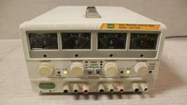
All good suggestions. In my case, I use a GW Instek bench supply to test amp boards before going "live". Since the supply has adjustable current limiting, you can very quickly determine if there is a board fault, simply by setting the current limit knobs to a low value, then ramping up the output voltages while watching the meters.
You need to set the supply up for series operation so that one side is in slave mode, and it will then track the master voltage control.
I got a used working unit on eBay in good condition for about $70 - well worth it. The only drawback of this particular unit is that it only goes to about +/- 32 volts on each rail, but that is sufficient to verify amp boards.
Attachments
Appreciate the input, didn't realise my DP832 could do a negative rail w/ the dual rails, will be able to test it at +/- 30V, 50mA and ramping up to calibrate - I feel much more confident now
Received replacements mosfets from arrow today (mouser/digikey are all out of stock, heads up people), I have maybe an hour of spare time for the next week so wont be until next weekend until I have something playing. My CNC guy is wrapping up cabinet parts and I can have them built for around next weekend too, so that's exciting.
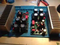
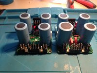
Progress pics
Zman01 et al,
Please see the attached pics of FH9HV & All Cees. I also posted the All Cees to be used with the Xmas amp.
The layout with the FH9 and All Cees diagonal to each other is OK ?.
Transformers will be on one side or possibly on an upper level ( I have an old humidor with 2 levels and plexiglass that I might try). SSR's may be between the two rows of amp & PS.
Waiting on hardware and starting to build various cables. Fun times😀
MM


That looks very neat and tidy, Myles. Nice work!
Diagonal placement is very pleasing to the eye.
Diagonal placement is very pleasing to the eye.
- Home
- Group Buys
- FH9HVX - Budget Conscious 100w Class AB for Lean Times
