Myles,
Is your question the following?
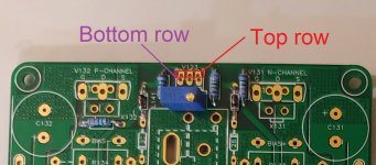
"Does the BD139 component get inserted in the top row or bottom row of PCB position V123?"
Image attached.
From looking at the two sets of holes, it looks like the holes in the top row are spaced at ~2.0 mm center to center, and for the holes in the bottom row the spacing is 2.54mm.
If I understand correctly, if you are using the JST connector specified in the bill of materials that Vunce has developed, the pins of the JST connector would fit in the 2.54 spaced holes.
If you are soldering the BD139 directly on to the PCB, then the pins will probably fit in the top row of PCB position V123.
Maybe X can confirm.
Also, Myles can you confirm if you are using the JST connector and cable for the BD139 and flying leads for the MOSFETs? Please note that all the 3 devices will need to be attached to the heat-sink within proximity of one another.
Is your question the following?
"Does the BD139 component get inserted in the top row or bottom row of PCB position V123?"
Image attached.
From looking at the two sets of holes, it looks like the holes in the top row are spaced at ~2.0 mm center to center, and for the holes in the bottom row the spacing is 2.54mm.
If I understand correctly, if you are using the JST connector specified in the bill of materials that Vunce has developed, the pins of the JST connector would fit in the 2.54 spaced holes.
If you are soldering the BD139 directly on to the PCB, then the pins will probably fit in the top row of PCB position V123.
Maybe X can confirm.
Also, Myles can you confirm if you are using the JST connector and cable for the BD139 and flying leads for the MOSFETs? Please note that all the 3 devices will need to be attached to the heat-sink within proximity of one another.
Attachments
Last edited:
Zman01 has it correct. The very top row is for direct mounting of BD139 temperature sensor (the so called “Vbe multiplier”). It needs to be in thermal contact with heatsink or preferable piggy back on one of the MOSFETs. I use the top Nchannel typically.
The griddle amp thread has lots of good closeup photos.
The Cast Iron Griddle Amp - a Budget Conscious Heatsink Solution
The griddle amp thread has lots of good closeup photos.
The Cast Iron Griddle Amp - a Budget Conscious Heatsink Solution
Last edited:
X and Zman01,
1. I will be using the flying leads, BD139 piggy backed on MFET on heat sink. as you both have in your builds.
2. The JST actually fits in top or the bottom row. Bottom row is sloppy fit, top row is slightly snugger fit, but not forcing.
3. If I am not mistaken the pads on the top row and bottom row are connected.
4. Given info in questions 1, 2, 3, where do you recommend I solder the JST module, top row or bottom row?
Thanks for the help,
Myles
Myles,
As you have correctly stated, the pins on the top row and bottom row are connected - so soldering to any of the rows will work. Just make sure that the 3 pins stay separate and that there are no solder bridges shorting any of then pins.
If I may ask, what chassis do you have in mind?
As you have correctly stated, the pins on the top row and bottom row are connected - so soldering to any of the rows will work. Just make sure that the 3 pins stay separate and that there are no solder bridges shorting any of then pins.
If I may ask, what chassis do you have in mind?
Technically, it is the bottom row but as they are connected, it doesn't matter. My JST 3-pin jack won't fit into the top row without bending the pins. Loose fit is fine as the solder holds it in place.
Thank you all, now I can proceed, bottom row it is.
Zman01 I have not chosen a chassis yet. My wife and I are creating some art pieces from resin expoxy and wood. I may make a custom chassis of resin and some beautiful BC wood that is plentiful around me. Have not decided on common heat sinks or a couple of cpu coolers. Coolers depend on whether I can fit both mosfets on a single cooler. Lot's of puzzles to solve with this great hobby. Back to soldering tomorrow
MM
MM,
That's a nice project that you are working on with your wife, and together you might be able to put together a unique looking chassis.
The aluminum sinks that I am using are roughly 150 mm x 150 mm, and weigh ~1 kg each. The base thickness is ~6 mm, and the fins are 30 mm. The sinks just get lukewarm, so possibly I can use smaller heat-sinks - I am guessing even 100 mm x 150 mm (for each channel) will do fine.
Zman01 and others,
I do have 2 pieces of 210mm x 140mm w/50mm fins that I could use for sinks. I was going to cut one of these in half length wise to get 210mm x 70mm x 50mm sinks, and use the 2 parts on the Xmas amp, and try the cpu coolers on the FH9.
I now am wondering if a 210mm x 70mm x 50mm may work for the FH9. I could use 2 of these for the FH9 and the Xmas amp.
Any thoughts on this.
MM
Thanks for the info X. One more quick question. Never soldered a transistor before. Enlarged your pics as much as I could, and it looks like you solder from the top. Do you also solder the bottom?. Very tight between pads on bottom, not sure if I can avoid solder bridge.
MM
MM
I solder from the bottom. Hold the tip for 10 second to let the solder flow and wick to the top side. If there is a bridge use copper solder braid wick to remove it.
X, are you using a fine tip (I have one) to solder these, I usually use a small chisel tip.
I was also looking at the small finned HS for the V124 and V129. Are they supposed to have a pin on each side to insert into a pad. Mine do not have this.
One more: Are you using nylon or metal washers to mount V124 and V129 to their HS.
Thanks for help.
MM
I was also looking at the small finned HS for the V124 and V129. Are they supposed to have a pin on each side to insert into a pad. Mine do not have this.
One more: Are you using nylon or metal washers to mount V124 and V129 to their HS.
Thanks for help.
MM
Hi MM,
Fine tip or small chisel tip - both should work. I used a fine tip for this project.
The support pins are not a must have for the heat-sink for V124 and 129. My HS did not have the support pins. I did not use any washers for V124 and V129. I did use a thin layer of thermal transfer compound (thermal paste) between the heat-sink surface and the device.
Just an advance tip - you will need to use thermal insulation pads for the P MOSFET and N MOSFET - you cannot have those in direct contact with the heat-sink.
Thanks zman01. I got a bunch of thermal pads on the way and I also have some K pads that I ordered from "tomchr" a while back. What I do have to pick up are small nuts and bolts. Not sure if I have any thermal paste so I may have to cut a K pad and use on the small heatsinks. More progress tomorrow.
MM,
I used the M3 machine screws and nuts. Have a mix of 6 mm, 8 mm, and 12 mm M3 screws in my parts bin.
Do you have a drill press?
I used the M3 machine screws and nuts. Have a mix of 6 mm, 8 mm, and 12 mm M3 screws in my parts bin.
Do you have a drill press?
I do have a bench top drill press. I drilled out the hole in the heat sink to accomodate a slightly larger bolt, but the bolt is just a bit to big to fit thru the transistor. I am going to pick up some M3's in various lengths also shortly. In the meantime I can start soldering my other FH9 pcb or the All Cees pcb. Lots to do, so not getting bored.
Myles
Myles
- Home
- Group Buys
- FH9HVX - Budget Conscious 100w Class AB for Lean Times