That’s a bit tight. I worry the stray EMI fields from trafo may induce hum. Can you rotate trafo and mount it against the front panel? Mount amp boards along the heatsink walls and PSU and SFP on floor. Keep trafo as far from input stage of amp as possible.
If that’s a 2U it won’t fit a standing trafo. Ideally the chassis should be bigger. It may work fine but won’t know how the EMI from trafo will be until assembled.
If that’s a 2U it won’t fit a standing trafo. Ideally the chassis should be bigger. It may work fine but won’t know how the EMI from trafo will be until assembled.
Last edited:
It looks like one of the shielded Anteks (AS series) - supposedly they have a bit of magnetic shielding around the outside, as well as a static shield between primary and secondaries, so it MIGHT be OK. Otherwise, how about a mu-metal barrier?
I have made some shields in the past with blank double-sided copper PCB boards with mu-metal layered on.
I have made some shields in the past with blank double-sided copper PCB boards with mu-metal layered on.
I don’t think that Antek has a shield wire.
I’d also be concerned with the AC mains wires passing right past the inputs for each amplifier board.
I’d also be concerned with the AC mains wires passing right past the inputs for each amplifier board.
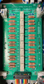
The preamp has a passive stepped attenuator and I/O selector controlled by an Atmega328 CPU - boards and some parts from Ti Kan at AMB Labs.Very nice work Wtnh! What do you have going for a preamp?
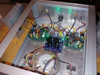
The case is a 2U Pesante from Modushop with some custom front-panel CNC machining done by them.
The volume control is actually a motorized pot that rotates in response to IR remote commands or can be manually rotated, and the microprocessor adjusts the stepped attenuator accordingly.
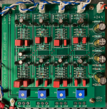
It also contains Nelson Pass's LXmini analog crossover, allowing bi-amplification (the reason for the 2 amps in this setup).
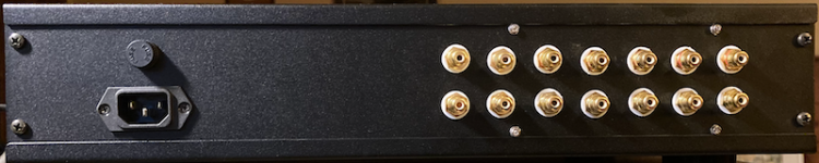
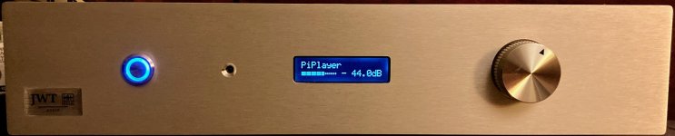
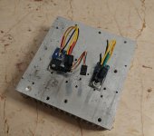
The second photo shows the relay-controlled attenuator board, the third shows Papa's crossover, and the 4th photo shows the rear panel - 4 sets of inputs and 3 sets of outputs (one regular and 2 high-pass/lo-pass). Last photo is the front panel showing the LCD display.
The power supplies are actually based on PCBs designed by DIY member iamwhoiam in this thread - the DeNoizator discussion. The 5 Volt digital supply omits the DeNoizator parts. I had the boards made by JLCPCB.
Building this thing is the reason it took me 4 months to finish the FH9 😀
Attachments

Last edited:
Thanks, guys. It was fun to build. I must admit to some head-scratching over the AMB Labs stuff, but after studying the schematics and reading Ti Kan's forum, I decided it was a cool approach.
So besides the Pass analog crossover for Lx mini, there is only AMB Labs/TiKan input select and stepped volume pot, no preamp stage with buffered gain?
So far, that's correct. The crossover does have JFET buffers on board, though. The signal levels have enough amplitude to drive the amps from my D/A converter.
With the AMB I/O board, there are send/receive busses and you can insert a gain stage in between them if you want to. In my case, they are jumpered together.
The real test will come when I have the LXminis done - with the FH9 driving the low end and the IF7 the uppers. If I can get about 80 Watts (the recommended power for the woofers) without added gain out of the FH9, I'll be good to go (although I do not typically listen to really loud music).
Another FH9HVX is born…
Got the parts for the amplifier boards towards the end of 2020, and have been slowly getting the other pieces (chassis, PSU, hand wound inductors) in place. Final assembly and testing happened yesterday.
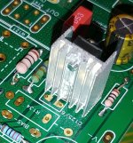
The FH9HVX PCBs were very easy to populate. Had to put a couple of parts on the underside of the PCB due to my choice of other parts; the heat-sinks I had chosen for V124 and V129 encroached on C123, C125, and hence put those (film) caps on the underside. For C106, I had chosen the wrong part number (electrolytic cap instead of a bipolar cap), but found a 220uF bipolar rated for higher voltage in my parts bin. The higher voltage cap was bigger, and hence C107 was sent to the underside of the PCB as well.
For the Molex Mini-Fit Jr harness to connect the flying leads to the PCB, I cheated and got readymade cables that are used for cable extensions inside PCs. I chopped off the unnecessary parts and had what I wanted. However, the wire is slightly thinner than what xrk971 and Vunce used for their flying leads, and is not as flexible – however it does the job nicely. I also used the small MOSFET PCBs to connect the MOSFETs to the flying leads.
For the power supply I used the Prasi’s compact CRC power supply PCB – great little PSU PCB. Caps are each 22,000uF, and for bleeder resistors have 2 x 2k7 Ohms in series giving 5k4 Ohms. The green LEDs I chose were unexpectedly bright! The chassis is borrowed from another project (that amp is getting bigger sinks and a taller chassis), and I had a few parts already installed like the rectifiers. I connected off-PCB rectifiers to the Compact CRC PSU PCB. As you can see, the chassis has loads of space inside, so placing everything was relatively pain free for me. 🙂 I placed the 2 amplifier PCBs and the PSU PCB on the floor of the chassis, and used flying leads to connect the MOSFETs to the heat-sinks.
The amplifier powered on without a hitch, and bias adjustment was easy. The offset voltages are low – one channel is around 1mV and the other is around 3 mV – that too without shorting the inputs (got lazy). My understanding is that the offset is adjusts automatically, so happy with the readings I got.
The amp has been playing since yesterday and I am liking what I hear with my test speakers. It sounds neutral with very good separation, clean mid-range, and solid bass. The speakers would be around 85dB sensitive and they go loud effortlessly. Plan to do critical listening with other speakers in the coming days.
Kudos to xrk971 for bringing this easy to build project to the DIY community. The bill of material cost is also modest. So, thank you X! Also thanks to JP for the PCB layout and Vunce for putting together the Mouser shopping cart links.
Off to some more listening. 🙂
Got the parts for the amplifier boards towards the end of 2020, and have been slowly getting the other pieces (chassis, PSU, hand wound inductors) in place. Final assembly and testing happened yesterday.
The FH9HVX PCBs were very easy to populate. Had to put a couple of parts on the underside of the PCB due to my choice of other parts; the heat-sinks I had chosen for V124 and V129 encroached on C123, C125, and hence put those (film) caps on the underside. For C106, I had chosen the wrong part number (electrolytic cap instead of a bipolar cap), but found a 220uF bipolar rated for higher voltage in my parts bin. The higher voltage cap was bigger, and hence C107 was sent to the underside of the PCB as well.
For the Molex Mini-Fit Jr harness to connect the flying leads to the PCB, I cheated and got readymade cables that are used for cable extensions inside PCs. I chopped off the unnecessary parts and had what I wanted. However, the wire is slightly thinner than what xrk971 and Vunce used for their flying leads, and is not as flexible – however it does the job nicely. I also used the small MOSFET PCBs to connect the MOSFETs to the flying leads.
For the power supply I used the Prasi’s compact CRC power supply PCB – great little PSU PCB. Caps are each 22,000uF, and for bleeder resistors have 2 x 2k7 Ohms in series giving 5k4 Ohms. The green LEDs I chose were unexpectedly bright! The chassis is borrowed from another project (that amp is getting bigger sinks and a taller chassis), and I had a few parts already installed like the rectifiers. I connected off-PCB rectifiers to the Compact CRC PSU PCB. As you can see, the chassis has loads of space inside, so placing everything was relatively pain free for me. 🙂 I placed the 2 amplifier PCBs and the PSU PCB on the floor of the chassis, and used flying leads to connect the MOSFETs to the heat-sinks.
The amplifier powered on without a hitch, and bias adjustment was easy. The offset voltages are low – one channel is around 1mV and the other is around 3 mV – that too without shorting the inputs (got lazy). My understanding is that the offset is adjusts automatically, so happy with the readings I got.
The amp has been playing since yesterday and I am liking what I hear with my test speakers. It sounds neutral with very good separation, clean mid-range, and solid bass. The speakers would be around 85dB sensitive and they go loud effortlessly. Plan to do critical listening with other speakers in the coming days.
Kudos to xrk971 for bringing this easy to build project to the DIY community. The bill of material cost is also modest. So, thank you X! Also thanks to JP for the PCB layout and Vunce for putting together the Mouser shopping cart links.
Off to some more listening. 🙂
Attachments
Last edited:
Great work there Zman01! Congratulations on a successful build and incident free start up. Using the premade PC connector wire harnesses is a great idea.
When you have a chance to listen more with your reference speakers let us know what you think.

When you have a chance to listen more with your reference speakers let us know what you think.
Nice looking work Zman01. Excellent that you had no incidents on p0wer up. I am just getting started so fingers crossed.
MM
MM
X,
It was a fun build thanks, will update once I have the other speakers connected and some more listening done.
Myles,
Thank you, and good to know that you are getting started. Please feel free to ask questions. Look forward to your build updates. 🙂
It was a fun build thanks, will update once I have the other speakers connected and some more listening done.
Myles,
Thank you, and good to know that you are getting started. Please feel free to ask questions. Look forward to your build updates. 🙂
Last edited:
For the Molex Mini-Fit Jr harness to connect the flying leads to the PCB, I cheated and got readymade cables that are used for cable extensions inside PCs. I chopped off the unnecessary parts and had what I wanted. However, the wire is slightly thinner than what xrk971 and Vunce used for their flying leads, and is not as flexible – however it does the job nicely. I also used the small MOSFET PCBs to connect the MOSFETs to the flying leads.
Nice job, Z! I like all the shiny aluminum. But hey - won't using computer parts on those flying leads color the sound

wtnh,
You will see most of my projects in shiny aluminum casings. The chassis are put together by yours truly, and I haven't been able to locate a good source of aluminum anodizing or painting yet. There are plenty of folks who will do a paint job, but when I ask if they will be using an etch primer, I don't get any answers, so I am guessing not. And therefore the raw aluminum stays raw...
Good comment about the computer parts. 😀 I'd like to blame X and JP - they came up with the Molex Mini-Fit Jr idea for MOSFET leads. 😉
Hello All,
I was planning to install the X121 3pin Molex header into the 3 holes for V123 (BD139) which is directly in front of R124. There is one more set of 3 holes in front of V123 which will be covered by the Molex header on the top side of pcb. Is this correct?
Also, the back plastic piece of X121 faces R124 as shown in 3D rendering in Post#85, Page 9. Is this the correct installation?
I looked at all the pics I could, but could not find a close up that showed what I questioned
above.
Feeling my way forward slowly. soldering all the passives. The inductor was a pretty hairy item to solder.
Myles
In general, the tab faces into the board for Molex KK connectors. But the one for the BD139 appears to be designed for a JST connector. In which case, the connector faces either way - there is a suggested outline on the pcb. It doesn’t matter as long as you are consistent.
Last edited:
Thanks X,
So to answer the first question the molex header is put into the V123 holes in front of R124, Correct?
MM
So to answer the first question the molex header is put into the V123 holes in front of R124, Correct?
MM
- Home
- Group Buys
- FH9HVX - Budget Conscious 100w Class AB for Lean Times