@namghiwwook,
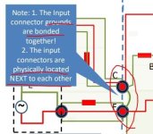
So you made sure the input connector grounds were grounded together and you also used an HBR?.
Did you also use a ground lift mechanism?
MM
So you made sure the input connector grounds were grounded together and you also used an HBR?.
Did you also use a ground lift mechanism?
MM
I have another problem.
Sometimes, its' Left/Right balance is not correct, then I must to adjust the L/R volume balance to 100 : 70 on the sound panel of MS Windows.
The gain of left channel happens to be dropped sometimes .... even during playing music.
Sometimes, its' Left/Right balance is not correct, then I must to adjust the L/R volume balance to 100 : 70 on the sound panel of MS Windows.
The gain of left channel happens to be dropped sometimes .... even during playing music.
Check for cold solder joints/poor soldering. Best way to check this is with a sinewave generator and oscilloscope, systematically checking every joint in the audio signal path. You will find one or many that are faulty. Check the RCA hot center pin. Typically that’s where the problem is.The gain of left channel happens to be dropped sometimes .... even during playing music.
In problems such as this it’s best to check in stages. This amp has an RCA input then input stage, VaS stage, driver stage, output stage, zobel/Boucherot cell/Thiele network and finally output binding posts. I usually work backwards starting at binding posts. I make comparisons between left and right channels. Try to UNDERSTAND the circuit. Read my post on page 70.
Remember there are times when a joint is intermittently conducting. That makes sleuthing difficult.
This is also a “thick” board with heavy amounts of copper. It requires a bigger heating element and more heat from the soldering iron. Use flux for your rework.
Best,
Anand.
@poseidonsvoice
Thank you!
I've re-flowed the pcb of the channel in trouble.
The problem has not ever happened in 4 or 5 days after that.
Thank you!
I've re-flowed the pcb of the channel in trouble.
The problem has not ever happened in 4 or 5 days after that.

The feedback resistor is 22k and the shunt to ground is 680R. So gain is 22k/0.68k or about 32x = 30dB.
So 875mV rms input will generate 28.3V rms into 8ohms for 100w.
So 875mV rms input will generate 28.3V rms into 8ohms for 100w.
Hmmm stupid question : I got an old Hypex smps at home with +-46V .... Can I use this one to power this amp ?
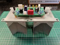
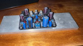
Slowly getting there with my FH9VX. I built the Prasi stereo board a good while ago but decided I couldn't get a satisfactory layout chassis wise, so have built a pair of monos.
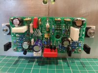
Not sure if these sinks will suffice. More aluminium to add to join them together yet.
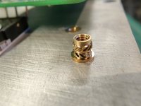
Found these nice little M3 inserts. Good time saver for those that don't like drill and tap. I don't mind that but thought I'd try them. Might be handy for copper CPU coolers. Didn't use them under the output MOSFETs though.
I have a 35v 500va donut to use which should give me somewhere around 50v. Haven't decided on PSU yet!
As usual a load of amp builds on the go but this one does intrigue me so is quite high up the list. My speakers came alive a bit more with 100 odd watts of 3255 class D up them compared to the low powered class A I had in before. (AN39 not included!).
Not sure if these sinks will suffice. More aluminium to add to join them together yet.
Found these nice little M3 inserts. Good time saver for those that don't like drill and tap. I don't mind that but thought I'd try them. Might be handy for copper CPU coolers. Didn't use them under the output MOSFETs though.
I have a 35v 500va donut to use which should give me somewhere around 50v. Haven't decided on PSU yet!
As usual a load of amp builds on the go but this one does intrigue me so is quite high up the list. My speakers came alive a bit more with 100 odd watts of 3255 class D up them compared to the low powered class A I had in before. (AN39 not included!).
Attachments
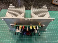
I have used similar Dell CPU cooler on a Class A amp with a fan. For Class AB, it might be enough for low level playing. If running high power maybe add a small fan.
I think those brass inserts are for installing in plastic to give them thread hard mounts. Those ridges on them are for melting into the plastic substrate. I have used them in my 3D printed parts.
I think those brass inserts are for installing in plastic to give them thread hard mounts. Those ridges on them are for melting into the plastic substrate. I have used them in my 3D printed parts.
Well that was a torrid few hours. got my PSU nicely built and giving 52.8v or something like that. First channel on test....quite a bit of DC and no current flowing through the output devices and bias won't adjust...hhmm.
After some reading I may have got T4 in backwards. I think I misinterpreted Prasis silkscreen. Swapped that over. Still no dice. Even more DC and still no bias current. Thought id try the other channel and it blew a cap on the neg rail which took at an R in my CRC neg rail. What I didn't realise is it also took both output FQAs. 😫.
Messed some more fixings the PSU and then managed to blow 2 more FQAs on the other channel.
Would not appear to be my day.
Anyone got Prasi single channel boards working?
Sorry I can’t help you there as those are not my boards. The XRK FH9HVX boards have been tested and guaranteed to work if parts properly installed.
When things don’t work, it’s generally MOSFET or BJT N or P mixed up or a resistor is off by 100 or 1000x in value. Or a diode or electrolytic is backwards.
When things don’t work, it’s generally MOSFET or BJT N or P mixed up or a resistor is off by 100 or 1000x in value. Or a diode or electrolytic is backwards.
Thanks X yes I appreciate that and understand this is your commercial thread. I found some members have the Prasi boards working fine so it must be me.
I also agree it must be an active in wrong or a diode backwards etc but I spent another unfruitful day removing the dead FQAs. Did some more tests. Replaced with IRFPs, which instantly blew.🙁
So I have had to take a step back from it for now for sanity.! I was pretty thorough in checking all the resistors so I'm a bit at a loss. I'll probably end up populating fresh boards but at the moment I'm not filled with enthusiasm for it!🙂
Jim,
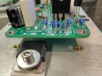
When you have some time, please post what your current board looks like, and also Prasi’s layout of your board if possible. In post 1533, I see that VR1 is not populated and I am not certain if T4 is mounted in the proper orientation. My recommendation is to have T4 mounted directly on a P-channel or N-channel MOSFET. For reference, I mounted my BD139 transistor directly on the N-channel Mosfet for accurate thermal tracking.

Best,
Anand.
When you have some time, please post what your current board looks like, and also Prasi’s layout of your board if possible. In post 1533, I see that VR1 is not populated and I am not certain if T4 is mounted in the proper orientation. My recommendation is to have T4 mounted directly on a P-channel or N-channel MOSFET. For reference, I mounted my BD139 transistor directly on the N-channel Mosfet for accurate thermal tracking.
Best,
Anand.
- Home
- Group Buys
- FH9HVX - Budget Conscious 100w Class AB for Lean Times