Has anyone built the FH9HVX with lower gain? I would like to have about 20dB gain instead of the standard 29dB.
Modern digital sources have ridiculous high output levels and i may also use a FE 2022 as a unity gain balanced to unbalanced converter. I realize that I may not have full output swing this way for a+-48V PS, but this is ok for me.
Modern digital sources have ridiculous high output levels and i may also use a FE 2022 as a unity gain balanced to unbalanced converter. I realize that I may not have full output swing this way for a+-48V PS, but this is ok for me.
Reducing the gain in most cases requires new values of the compensation capacitors. A simulation might help.
See my build on page 70 - specifically under the heading 'Ingredients.'Has anyone built the FH9HVX with lower gain? I would like to have about 20dB gain instead of the standard 29dB.
Modern digital sources have ridiculous high output levels and i may also use a FE 2022 as a unity gain balanced to unbalanced converter. I realize that I may not have full output swing this way for a+-48V PS, but this is ok for me.
To be short, no, I didn't change the overall gain of the FH9HVX for precisely the reason jorgovanko stated. Instead I reduced the gain by 6 dB at the input.
Best,
Anand.
Ideally, running a simulation followed by bench testing should be done. Compensation caps in the end are best done empirically by use of an o scope checking for oscillation. If you want to try it - you can help the DIYA community.
Change R108 to 2k2 and check for oscillation. Slowly increase C141 to a higher value. 10pF then 15pF. Use the smallest value that stops the oscillation. It may not oscillate at all. Use a 10W 8ohm dummy load at amp output.
Alternatively, you can change a combination of R108 and R141 such that (R141/R108) = 10 (or 20dB).
Such as 15k/1.5k etc. that only deviates from nominal values on either by lower amount.
In any case, start with nominal values first to make sure the amp works. Then adjust gain.
Nice build Anand, and a good set of measurements. Read everything up to last spring but then went off DIYA for some time.
I might even reduce gain further at the input when(if) FE 2022 is implemented. They were a real hit on the input for my F6!
I might even reduce gain further at the input when(if) FE 2022 is implemented. They were a real hit on the input for my F6!
Hello Forum Members,
I am starting from scratch on this thread in my efforts to find the source of the buzz in my FH9HVX. My apologies to those who were following my poorly placed posts on this subject last month. I am the primary caregiver for someone with a progressive health condition and I had become spread thin and burned out.
Now...back to business. The hum in my FH9HVX started after I installed a remote soft start board in my amp. The installed board works perfectly but now I have noise.
Initially I was intending to install a ground lift but as Anand so graciously pointed out, several of the components in my amplifier already incorporate ground lift circuitry. Realizing that I was looking for a solution without knowing what the problem is, I downloaded How to Wire-up an Audio Amplifier by Andrew Russell. What an amazing resource.
One of the first issues I noticed was that my grounding scheme was incorrect. I had my PE ground running from the IEC to a star ground, then back to the chassis. Not only did this violate the rule of grounding the chassis first I believe it created an internal loop inside the amp that encircled much of the AC circuitry. This was fixed following Mr. Russell's guidelines. The noise is now much quieter, but is still there. One clue that seems important in my mind is that the noise does not get louder as the volume is increased. Does this suggest the source is down range from the signal circuitry?
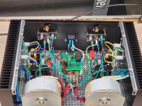
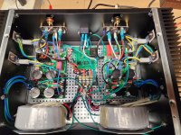
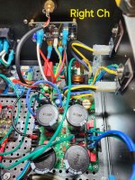
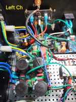
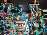
My amp was wired along the lines of rat's nest approach with wires criss-crossing in many areas making my job more difficult. I am considering tearing the amp down and rewiring it from square one with more attention paid to wire dressing. Right now the amp is all buttoned up so I don't have any recent pics to share. I have included a couple taken before I installed the soft start just to illustrate the lay-out. Any ideas where I should start?
Attachments
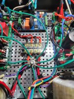
Since the noise started after installing the remote soft start, let's start with that. Which soft start was used and a picture of how it is wired. More than likely, something about how the soft start is wired is causing your problem.
Your main IEC ground seems awefully long and runs close to the AC Secondaries. Have you tried to shorten this wire and possibly attached directly to the bolts holding in the IEC plug/switch? You could cut off 6-8 inches and if needed add a CL-60 between the wire and screw/bolt to provide a ground lift.
Hi RickRay and Bullitstang,
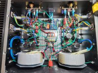
Thank you for your responses. I have now included current photos of the amplifier. The soft start I installed was a Neurochrome Intelligent Soft Start which seems to work great. One crucial factor that wasn't included in my initial post is that the buzz is confined to the left channel only. I'm hoping that narrows my search.
I can provide more/better pics if needed. Thanks guys.
Attachments
Can you tell us which board is "Left", is it actually the left in the picture, because the RCA looks red?
If your bolt on the back panel has continuity to the Star Ground - you shouldn't need another wire coming from that IEC ground connection. I would contend that the IEC is only being grounded to facilitate a low resistance to ground in case of short circuit to blow the fuse as quickly as possible. I wouldn't mix the two points by adding the extra wire to the star ground.
If removing the extra wire to IEC doesn't help, I would try adding a CL-60 to the IEC wire before termination to the back panel. You could start with a 10-r resistor if you don't have a CL-60 to "test" if the ground lift has any impact to the hum issue before committing to purchase.
One thing I notice is no twisting of wires.
This one can make a big difference. Pairs of wires should be twisted. Triplets of wires should be braided. As tight as possible.
I like to cover twisted/braided wires with clear heatshrink as this allows a really tight twist to be held in tension so it doesn't untwist.
This one can make a big difference. Pairs of wires should be twisted. Triplets of wires should be braided. As tight as possible.
I like to cover twisted/braided wires with clear heatshrink as this allows a really tight twist to be held in tension so it doesn't untwist.
To be clear. There should be nothing but wire between the EIC ground and the chassis, which you currently have with the short green wire from the EIC plug to the chassis. If the star gound is connected to the chassis, which it apears to be, you have two paths to the chassis gound from your star-ground, not good. Remove the long green wire between the chassis ground and star ground. If this does not fix it, I would remove the star ground and install it in some way insulated from the chassis. Then attach the CL-60 between the insulated star ground and chassis ground. You ALWAYS want the EIC plug ground going directly to the chassis with nothing in between.
That long green wire running right next to the input section of your left channel. I'm suspecting that. Twisting the wires is always a good practice.
Hi Bullitstang,
Yes that is indeed the left channel, although I mistakenly put the wrong color RCA on that side. This was my first build and there are many things I would do differently.
As far as the ground issue, should I remove the ground wire from the IEC to the star ground? The connection between The IEC and the back panel is crucial for safety correct? Thanks for your assistance.
Sadface,
Thanks for your response regarding twisting wires. I need to seriously work on my wire dressing. Point taken.
Thanks for your response regarding twisting wires. I need to seriously work on my wire dressing. Point taken.
Thanks RickRay,
I was pretty sure the connection between the IEC and the chassis was crucial. I was less sure about the grounding of the rest of the amp.
I have enough information here to make some changes and report back in the morning. Thanks guys, I genuinely appreciate the help.
I was pretty sure the connection between the IEC and the chassis was crucial. I was less sure about the grounding of the rest of the amp.
I have enough information here to make some changes and report back in the morning. Thanks guys, I genuinely appreciate the help.
Take your time and try to enjoy it.Sadface,
Thanks for your response regarding twisting wires. I need to seriously work on my wire dressing. Point taken.
Wiring is one of those final steps that can be tempting to rush but is worth the effort.
I like to go crazy with heatshrink, ptfe braid, cable ties, p clips etc. A gorgeous wiring job gets me in the feels.
Hello Forum Members,
So I removed the green ground wire running from the chassis to the star ground. That was the only change I made.
With no rca jacks connected to the amplifier I get a faint hum from both speakers. Actually, I could live with that if I had to but...when I connect the rca's to the amp I get a god-awful loud buzz from the left speaker. I think before I do anything else I'm going to get a different rca cable, and closely examine the left rca receptacle on the amplifier for shorts or loose connections. Something is not right on that channel.
I won't have time to work on this further until late today or early tomorrow. I'll keep everyone posted. I'm in need of a winter project. I still haven't ruled out tearing the amp down, mounting the boards and output transistors on the heatsinks, and treating the amplifier to a more disciplined wiring job. This is the favorite of my two class AB amps.
Thanks for following guys, I appreciate your time.
- Home
- Group Buys
- FH9HVX - Budget Conscious 100w Class AB for Lean Times
