Hey Kelly T,
I'm not clear on what you mean by separating the earth grounds.
Would that basically be a star ground for each channel? If so, that would be easier to wire in my estimation. Thanks for all the pointers by the way!
I'm not clear on what you mean by separating the earth grounds.
Would that basically be a star ground for each channel? If so, that would be easier to wire in my estimation. Thanks for all the pointers by the way!

Hello Forum Members,
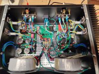
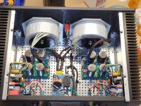
I've completed rewiring my FH9HVX. I've attached before and after pics.
AC level mains have been confined to the center of the chassis. They have been twisted, covered in heat shrink, and (for the most part) covered in PET braided sheathing.
Amplifier boards were mounted directly to the heat sinks which necessitated new output transistors. In a stroke of luck, I managed to catch Mouser when they had both varieties in stock.
Other wiring was shortened when possible. I used two star grounds, one for each channel.
The next step is testing and setting the bias. I will probably do that tomorrow morning. Unfortunately, if I run into any significant roadblocks, the amp will likely be boxed up for awhile as my wife and I have decided to sell our home. I need to get going on prepping for the move.
Tomorrow is the big day, wish me luck!
Attachments
Gorgeous!
What a huge improvement.
That looks like a few evenings work.
Super tidy wiring is hugely enjoyable imo.
Take your time, listen to something, maybe a bit of your favorite poison on the side. Down right cathartic.
What a huge improvement.
That looks like a few evenings work.
Super tidy wiring is hugely enjoyable imo.
Take your time, listen to something, maybe a bit of your favorite poison on the side. Down right cathartic.
Kelly T, UncleMud,
Did you run 2 IEC ground wires from the mains inlet for the 2 separate star grounds to keep them completely separate?. Hard to tell from the pic's. I also have to redo my wiring at some point to solve hum problems.
Thanks
Did you run 2 IEC ground wires from the mains inlet for the 2 separate star grounds to keep them completely separate?. Hard to tell from the pic's. I also have to redo my wiring at some point to solve hum problems.
Thanks
Kelly T, UncleMud,
Did you run 2 IEC ground wires from the mains inlet for the 2 separate star grounds to keep them completely separate?. Hard to tell from the pic's. I also have to redo my wiring at some point to solve hum problems.
Thanks
yes that is what I did, I also put the purple shielding wire on the star grounds, I do not know if that is necessary, but I have always set the ground up that way. It is the way 6L6 did it in the Aleph J build guide. I have not built FH9HVX, my build have been limited to a hand-full of class A amps at this point, so I am no expert.
Last edited:
Hello Forum Members,
My FH9HVX powered up just fine except for some confusion getting the switch wired to the ISS correctly.
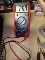
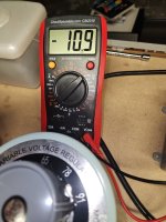
Quick question: The left channel dialed up to 26.0 mV DC with -3.5 mV of offset. However, when I brought the right channel up to -26.0 mV, the offset was -10.9. With the DMM set to the 200 mV scale this should still be well within limits correct? Can I get a thumbs up or down?
(It's quite early in the morning and my mental conversion skills are not fully functioning yet).
My FH9HVX powered up just fine except for some confusion getting the switch wired to the ISS correctly.
Quick question: The left channel dialed up to 26.0 mV DC with -3.5 mV of offset. However, when I brought the right channel up to -26.0 mV, the offset was -10.9. With the DMM set to the 200 mV scale this should still be well within limits correct? Can I get a thumbs up or down?
(It's quite early in the morning and my mental conversion skills are not fully functioning yet).
Attachments
I found the answer online folks. Sorry to bother for something so trivial. Next step, speakers.
I always thought this amplifier PCB is 100% compatible with the Alpha Nirvana or the same. (I have a set of PCB of this amp).
(I only interested in Class A as my next project!)
Tonight I compared the two project and their PCB. How wrong I was about that. 😴 😱
I heard so much good about the AN 39Watt type I thought lets start to collect some parts and build the amp sometimes in the future...
Thank God first I look up the PCB design to find out the two is total different cup of tea.
I also have a pair stuffed PCB the 20W type?? blue color, not sure if I ever test that knowing the AN 39W type is much better🙁.
I do not like just to test an amp and give it up!
I must go over the treads, this one and the AN also to learn more about them.
To be honest I did not follow either of the mentioned threads. Reason; I was sure until now the AN only works with forced air cooled heatsink.
Now I will follow..........
Attachments
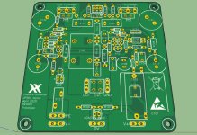
The Alpha Nirvana and FH9HVX PCBs both have options for externally mounted MOSFETs but that’s about all that’s in common. You could use the same MOSFEts and chassis but the PSU voltages are different. The FH9HVX is a wonderful sounding amp and capable of 150w output. Some people need that extra oomph with low sensitivity speakers.I always thought this amplifier PCB is 100% compatible with the Alpha Nirvana or the same. (I have a set of PCB of this amp).
(I only interested in Class A as my next project!)
Tonight I compared the two project and their PCB. How wrong I was about that. 😴 😱
I heard so much good about the AN 39Watt type I thought lets start to collect some parts and build the amp sometimes in the future...
Thank God first I look up the PCB design to find out the two is total different cup of tea.
I also have a pair stuffed PCB the 20W type?? blue color, not sure if I ever test that knowing the AN 39W type is much better🙁.
I do not like just to test an amp and give it up!
I must go over the treads, this one and the AN also to learn more about them.
To be honest I did not follow either of the mentioned threads. Reason; I was sure until now the AN only works with forced air cooled heatsink.
Now I will follow..........
@Chrisr3521,
40v secondaries will get you 56Vdc. You can double check with Xrk but if memory serves me correctly, that would be the max I think.
40v secondaries will get you 56Vdc. You can double check with Xrk but if memory serves me correctly, that would be the max I think.
I have run at +/-52v so I think should be ok at +/-56v. Make sure your caps are rated appropriately. The actives should be fine.@Chrisr3521,
40v secondaries will get you 56Vdc. You can double check with Xrk but if memory serves me correctly, that would be the max I think.
Great thanks, I'll check the schematic for the caps.
Powersupply smoothing caps would be OK at 63v, around a 12% buffer?
Powersupply smoothing caps would be OK at 63v, around a 12% buffer?
- Home
- Group Buys
- FH9HVX - Budget Conscious 100w Class AB for Lean Times