You can also just switch RCA cables from one channel to the other and see if the noise follows the cable.


Hello Forum Members,
Wanted to update anyone who may be curious regarding my FH9HVX buzz issue. Unfortunately, by the time I read the advice about swapping cables I had already pulled the amp from the rack. (Why didn't I think of that?)
I unhooked both rca inputs from the amplifier boards and checked the connectors and cables for shorts. They seem fine. The rca to rca interconnect cable I was using between the amp and preamp was a cheap one and the end was deformed. It didn't show any internal shorts but I threw it out anyway.
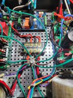
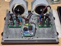
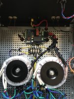
I'm going to put aside that heart-stopping buzz issue related to the cable for now. (Remember I actually had a significant left channel buzz before the rca cable incident). In examining the left amplifier board I noticed that the AC outputs from the soft start board exit right next to the left channel signal input. As a matter of fact, one AC level red wire almost touches the input connector to the amplifier board. That can't be good. This would make sense as one probable source for my left channel buzz since: 1. I don't hear it until after the soft start engages. 2. It didn't start until after I installed the soft start board.
I'm thinking about rotating the board 90 degrees and paying more attention to wire dressing as I go. I've included one close-up pic of the input and one wider angle shot. Feel free to add any suggestions.
Wanted to update anyone who may be curious regarding my FH9HVX buzz issue. Unfortunately, by the time I read the advice about swapping cables I had already pulled the amp from the rack. (Why didn't I think of that?)
I unhooked both rca inputs from the amplifier boards and checked the connectors and cables for shorts. They seem fine. The rca to rca interconnect cable I was using between the amp and preamp was a cheap one and the end was deformed. It didn't show any internal shorts but I threw it out anyway.
I'm going to put aside that heart-stopping buzz issue related to the cable for now. (Remember I actually had a significant left channel buzz before the rca cable incident). In examining the left amplifier board I noticed that the AC outputs from the soft start board exit right next to the left channel signal input. As a matter of fact, one AC level red wire almost touches the input connector to the amplifier board. That can't be good. This would make sense as one probable source for my left channel buzz since: 1. I don't hear it until after the soft start engages. 2. It didn't start until after I installed the soft start board.
I'm thinking about rotating the board 90 degrees and paying more attention to wire dressing as I go. I've included one close-up pic of the input and one wider angle shot. Feel free to add any suggestions.
Attachments

Hi X and all other builders,
Sorry to intrude on this hum problem hunt. I was wondering if I could use the heat pipe type cpu coolers without a fan on this project. I have lots of these coolers and since the heat sink temps are 35-45C, is it possible to one operate without a fan. I am thinking of using 1 cooler per amp board. I would appreciate thoughts on this, just trying to use what I have on hand.
I could even use 1 cooler for each transistor, if I had too.
Thanks,
MM
@UncleMud I think your idea to turn 90-degree is a good one, being right by the input is a good chance it's picking up stray AC.
Also, as mentioned earlier take this time to twist any AC wires tightly, so IEC to soft-start board, then soft-start to trminal block, terinal block to the transformers. I do it, and would suggest you also twist the wires going to and out of the power supply boards.
paying attention to routing wires as far as possible from the Inputs, on amp board and mounted to case.
Then you might start with the left channel and see if you can get it playing hum free by itself, then add in the right channel and see if it's still hum free. Take as many variables out of the equation as possible.
Hello Forum Members,
Update on my buzz issue with my FH9HVX. In examining my amplifier more closely I have discovered that the transformers have settled on the L brackets and are touching the base. I'm concerned that with time the covering could wear through and allow the turns to contact the chassis. I have ordered larger, more robust brackets. This along with the haphazard approach of my initial wiring job has convinced me that I need to completely rewire the amp. I plan on using suggestions made here to improve my technique. Twisted pairs, heat shrink. PET braided covering, etc. I will keep everyone here up to speed. When I'm done I will post the results with before and after pics. Thanks everyone!👍
Update on my buzz issue with my FH9HVX. In examining my amplifier more closely I have discovered that the transformers have settled on the L brackets and are touching the base. I'm concerned that with time the covering could wear through and allow the turns to contact the chassis. I have ordered larger, more robust brackets. This along with the haphazard approach of my initial wiring job has convinced me that I need to completely rewire the amp. I plan on using suggestions made here to improve my technique. Twisted pairs, heat shrink. PET braided covering, etc. I will keep everyone here up to speed. When I'm done I will post the results with before and after pics. Thanks everyone!👍
Did you use lock washers on the toroid mounting bolt? I did, and I just checked, my transformers are still as tightly connected as the day I closed up the amp. I don't recall if I used the bolt that came with the L bracket or the bolt that came with the Antek transformers, but I can say for certain I would have used whatever was beefiest.
Looking forward to seeing your spruced up build.
Looking forward to seeing your spruced up build.
Hi BH,
Yes, I used lock washers but the initial clearance between the toroid and the base was so small they slid down ever so slightly making contact. The new brackets should remedy this. Thanks for asking.
Yes, I used lock washers but the initial clearance between the toroid and the base was so small they slid down ever so slightly making contact. The new brackets should remedy this. Thanks for asking.
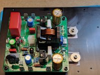
I completed my build of the FH9HVX last week. All the plans for a case and separate PS case fell through, or at least is more or less delayed. Instead of waiting, plan B was set in motion, use a smaller 36V transformer and a few of the power supply components I had in store. A bad computer power supply case had to make do.


I decided to build the amplifier as cheap and easy as I could so an Ikea bamboo tray was sacrificed. The heat sinks is from a scrapped project from work.
Anyway, the build looks quite nice I think. Shielding of the amplifier is non existent but still, it is dead quiet. Gain is as on the original 30(32?) dB.
Sound is as a lit of others has described it, very dynamic and engaging, good all around. As a friend said - a very good amplifier for watching movies. It lacks a little of the warmth for music. A thing I will try to remedy in a while.


Components; no components was harmed during the build (except I put the led's the wrong was around af first). Mosfets are FQA40N25 and P15. I got the P15 from Italy via Ebay. I got a brain fart during the build, if the BD139 transistor is shut off all the current is going through the P channel mosfet and not much is going to work.
At some point I will replace the inductor with the nice looking one, the one in the picture just looks horrible, even if it works.
The amplifier is barely warm during normal operation, current is set to a smidge less than 100 mA. Measurements will follow shortly, and just before writing this message I have set gain to 20 dB. All stability measurements (except gain) looks to be the same.
I haven't done any distortion measurement yet, that will be for another time.
I decided to build the amplifier as cheap and easy as I could so an Ikea bamboo tray was sacrificed. The heat sinks is from a scrapped project from work.
Anyway, the build looks quite nice I think. Shielding of the amplifier is non existent but still, it is dead quiet. Gain is as on the original 30(32?) dB.
Sound is as a lit of others has described it, very dynamic and engaging, good all around. As a friend said - a very good amplifier for watching movies. It lacks a little of the warmth for music. A thing I will try to remedy in a while.
Components; no components was harmed during the build (except I put the led's the wrong was around af first). Mosfets are FQA40N25 and P15. I got the P15 from Italy via Ebay. I got a brain fart during the build, if the BD139 transistor is shut off all the current is going through the P channel mosfet and not much is going to work.
At some point I will replace the inductor with the nice looking one, the one in the picture just looks horrible, even if it works.
The amplifier is barely warm during normal operation, current is set to a smidge less than 100 mA. Measurements will follow shortly, and just before writing this message I have set gain to 20 dB. All stability measurements (except gain) looks to be the same.
I haven't done any distortion measurement yet, that will be for another time.
Well, measurements is sooner than later. My idea to test stability is to feed the amplifier a square wave signal and have a resistive load and in addition a capacitor across the load. This may or may not be optimal, but it is my test. The resistor is 8 ohms and an added 1 uF PP capacitor. Output from the amp is always set to 20 V p-p.
Left and right channel was measured. They had the same measurements to a fault.
I don't remember if the "standard" gain is 30 or 32 dB, it is just a guess from my part.
First off; standard gain and build, 1 kHz and 10 kHz with just 8 ohm load.


Then 1 kHz and 10 kHz with 8 ohm paralleled with 1 uF.


Then i lowered the gain to (about) 21 dB and used a 22 pF capacitor (up from 4.7 pF) with the feedback resistor. I'm not going to bore you with the screen shots. It is very near the same behaviour regardless of gain.
Bonus shot, 50 kHz, 8 ohm load, exactly the same p-p output as for lower frequencies.

Left and right channel was measured. They had the same measurements to a fault.
I don't remember if the "standard" gain is 30 or 32 dB, it is just a guess from my part.
First off; standard gain and build, 1 kHz and 10 kHz with just 8 ohm load.
Then 1 kHz and 10 kHz with 8 ohm paralleled with 1 uF.
Then i lowered the gain to (about) 21 dB and used a 22 pF capacitor (up from 4.7 pF) with the feedback resistor. I'm not going to bore you with the screen shots. It is very near the same behaviour regardless of gain.
Bonus shot, 50 kHz, 8 ohm load, exactly the same p-p output as for lower frequencies.
Hello Forum Members,
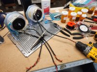
A brief update on my rewiring project. The new brackets hold the toroids up off the base nicely. Secured with 5/16" bolts and lock washers, they should stay put.
The cordless drill is working well to twist the primary AC wires. So far, so good.
A brief update on my rewiring project. The new brackets hold the toroids up off the base nicely. Secured with 5/16" bolts and lock washers, they should stay put.
The cordless drill is working well to twist the primary AC wires. So far, so good.
Attachments
Hello Forum Members,
Quick question for anyone who can offer their experience.
I would like to cover my twisted AC primary wires with braided copper sleeve and finish with PET braided sleeve for insulation and cosmetics.
Is there any downside to covering the AC inputs with braided copper? I'm trying to reduce any potential sources of noise. I'm sure it's overkill. (But that's my middle name).🙂
UncleMud,
I am very new to this, however the way you hooked up your dual transformers to the ISS if it is from Neurochrome might be an issue. Please take what I am writing with a grain of salt. I just completed a dual mono build and I had to put the 1 primary from one doughnut into the same spot on the soft start as the one primary from the second doughnut, I use bootlace connectors and placed red 1 red 1 from each transformer into the proper connection on the ISS. I repeated this step matching black 2 black 2 ……. you should get continuity from 1-2 and have just a few ohm’s, the same with 3-4.
I am very new to this, however the way you hooked up your dual transformers to the ISS if it is from Neurochrome might be an issue. Please take what I am writing with a grain of salt. I just completed a dual mono build and I had to put the 1 primary from one doughnut into the same spot on the soft start as the one primary from the second doughnut, I use bootlace connectors and placed red 1 red 1 from each transformer into the proper connection on the ISS. I repeated this step matching black 2 black 2 ……. you should get continuity from 1-2 and have just a few ohm’s, the same with 3-4.
Attachments
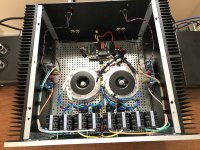
Made a little progress on my rewiring project:
-New L-brackets now give a good 1/2" clearance between toroid and base.
-Amplifier boards are now mounted directly to the heatsinks eliminating flywires to the output transistors.
-New L-brackets now give a good 1/2" clearance between toroid and base.
-Amplifier boards are now mounted directly to the heatsinks eliminating flywires to the output transistors.
Attachments

looking good @UncleMud and well on your way to a great amplifier that's quiet!
Nothing against the design and what DIYers choose, but I think it looks more polished to remove the fly-wires (if it can be). But I'm guilty of rushing to hear a new amp build too, and I'll use fly-wires to avoid drilling and tapping. At least until the amp build earns the stamp of approval.
Nothing against the design and what DIYers choose, but I think it looks more polished to remove the fly-wires (if it can be). But I'm guilty of rushing to hear a new amp build too, and I'll use fly-wires to avoid drilling and tapping. At least until the amp build earns the stamp of approval.
Thanks @bullittstang . That's exactly what happened too. It was my "first" build and I was in a hurry to see if it would work. I've since slowed down. And I like this amp so much I feel it's worth the effort to do it properly.
@Kelly T . I understand what you were describing with the primary connections to the ISS. Can't believe I didn't think about that myself. Have some double-wire ferrule connectors coming today. Thanks for the heads-up!
@Kelly T . I understand what you were describing with the primary connections to the ISS. Can't believe I didn't think about that myself. Have some double-wire ferrule connectors coming today. Thanks for the heads-up!
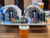
Making modest progress on my FH9HVX rewiring project. All mains-level AC wiring is twisted, shrink-wrapped and covered with PET braided outer covering. They are also confined to the center of the chassis, with transformers in the very front. Amplifier boards are mounted directly to the heat sinks in the center-rear of the cabinet, a good 4-5 inches from mains and transformers.
One step at a time!👍
One step at a time!👍
Attachments
UncleMud- outstanding wire managment! Taking your time and testing on the way seems to really help the end results. I split my earth ground between the two separate power supplies (different than the picture in my first post), I did not know if you were going to do the same or make a single star ground. It worked either way for my build, the only noticeable difference was a completely silent background when I separated them. If you are now is the time, it was tough after the build was complete.
Attachments
- Home
- Group Buys
- FH9HVX - Budget Conscious 100w Class AB for Lean Times