Are these pcb's tested?i have some irfp260n hexfet mosfets.will a quasi complementary output work with this amplifier?if yes will there be any layout??
there are 2 nice layouts for one pair of output transistors 2sc5200/1sa1943. has anyone tested both?does one sounds better than the other ??
Thank you Borys. There's only available 9240 from a reliable distributor (no 9140). I'm going to replace the amp section of a powered sub with this one, parts are easily available (no counterfeits). Sub is 100W rated and rails are +/- 40V. It´s more convenient to use bootstrap version (is BG1 bootstrapped)? It´s safer to use MJE´s instead BDs as I intend or there is no benefit?
I'm thinking of using the ALFET (SEMELAB) ALF16N16W and equivalent PNP in my watercooled amplifier. http://www.diyaudio.com/forums/soli...ooled-hexfet-power-amplifier.html#post3867732
The ALF16N16W needs 1.5V bias to turn on I believe. Would this circuit be suitable for the ALF16N16W, would the BD140 be capable of driving it? I suspect Q11 may not be the best for controlling the bias as it wont match the ALF16N16W when temperature rises.

Cheers
Dom
The ALF16N16W needs 1.5V bias to turn on I believe. Would this circuit be suitable for the ALF16N16W, would the BD140 be capable of driving it? I suspect Q11 may not be the best for controlling the bias as it wont match the ALF16N16W when temperature rises.

Cheers
Dom
Q10 is upside down.
Why an irf540 for Q11?
Why no drivers between the dual VAS stage and the outputs?
1.5Vgs to turn on the outputs. Did you read the datasheet?
The bd139/140 should not blow up with +-38Vdc supplies.
I have not looked at your input stage.
Pchannel lateral mosFET.equivalent PNP
Why an irf540 for Q11?
Why no drivers between the dual VAS stage and the outputs?
1.5Vgs to turn on the outputs. Did you read the datasheet?
The bd139/140 should not blow up with +-38Vdc supplies.
I have not looked at your input stage.
Well, it's only the gate, which is drawn upside down - the source, drain and protection diode are ok.
Q10 is upside down.Pchannel lateral mosFET.
Why an irf540 for Q11?
Why no drivers between the dual VAS stage and the outputs?
1.5Vgs to turn on the outputs. Did you read the datasheet?
The bd139/140 should not blow up with +-38Vdc supplies.
I have not looked at your input stage.
Upside down? Can you elaborate?
I only have two ALF16N16W and two ALF16P16W so don't have any spare for the bias.
The last circuit using the IRF9540/540 didn't require drivers. Would you suggest using drivers for larger output MOSFETS?
Yes. See below.

That's a pic of the Nchannel Lateral mosFET
Download the Pchannel complement.
You are using the BD VAS to drive the mosFET outputs.
The SOA @ 25°C limits it's maximum current to <200mA @ 38Vce. 7.6W @ Tc=25°C
That should be plenty reserve to drive the FET capacitance if you allow the VAS to run warm rather than hot.
The 540 is a voltage regulator.
It takes no part in driving the mosFET capacitance.
Last edited:
N-channel only
There is schematic for using N-channel mosft only??
Which post can show it??
thanx
Regards
There is schematic for using N-channel mosft only??
Which post can show it??
thanx
Regards
Last edited:
Sorry I did not tryed any darlingtons yet. I have no experirience with TIP darlingtons (speedwise). Wit a bit higher values of the compensation caps they should work well.
Thank you for answering Borys.
The simulation with darlingtons gives very good results.
I also have a Darlington circuit at another thread
Please keep inform us with your progress. Also interested .............🙂
Thank you
Greetings
Yes I have seen the other thread.
I have lots of Darlington in my drawer and I 'd already made an amplifier with these transistors to the sumptuous sound.
I have several simulations with these transistors but I 've not yet gone to completion.
I will go here when I do the tests.
I have lots of Darlington in my drawer and I 'd already made an amplifier with these transistors to the sumptuous sound.
I have several simulations with these transistors but I 've not yet gone to completion.
I will go here when I do the tests.
What I built it was the best sounding amplifier I ever built, all do it had some thermal drifting issues.
I built a lot over 25 years .
Can you simulate my circuit , I will invite you to that thread.
Greetings
I built a lot over 25 years .
Can you simulate my circuit , I will invite you to that thread.
Greetings
Ok I have a silencer to change on my car this afternoon and I do the simulation on the other.Can you simulate my circuit , I will invite you to that thread.
Greetings
There is schematic for using N-channel mosft only??
Which post can show it??
thanx
Regards
difficult to find complementary mosfet in indonesia pak Thole?me too
please see my schematic, can someone run simulation for me?
Attachments
difficult to find complementary mosfet in indonesia pak Thole?me too
please see my schematic, can someone run simulation for me?
I use models from Bob Cordell except BC546B, BC556B, and IRF510.
I set mosfet quiscent current about 180mA.
Result:
Phase Margin = 87
Gain Margin = 24
Slew rate = 196 V/uS
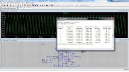
THD see attachment, it seem too high.
Attachments
thank you pak Bimo
i am still learning how to use ltspice for audio simulation from mooly's thread
can you share your simulation setup parameter so i can try to optimize it?
i am still learning how to use ltspice for audio simulation from mooly's thread
can you share your simulation setup parameter so i can try to optimize it?
- Home
- Amplifiers
- Solid State
- FET-hex explendit amplifier