Okay, one point of that list is when picking 1 that sims well, then you don't have to make a lot more designs to support many other parts. Just 1 will do when its so highly available. Maybe this is easier in the long run? Well, I hope so.
After all of this, I still have to ask, why not just make one of the amps inverting and one non-inverting, so no phase splitter is needed? Too "asymmetric"?
Or, if you really want to use two identical power amps, then why not just use two simple unity-gain opamp input buffers, with one being inverting and one being non-inverting? Still too asymmetric?
Or is it really just too boring that way?
Or, if you really want to use two identical power amps, then why not just use two simple unity-gain opamp input buffers, with one being inverting and one being non-inverting? Still too asymmetric?
Or is it really just too boring that way?
Tom, wow! Asymmetry? That's a really big question!
Apparently what matters is that a square wave be precisely the same sort of square. So, I have no other choice but to answer that yes, asymmetry is a potential problem for sounding a lot like a car amp chip. How much of a problem? That I do not know.
With chips, possibly post 46 needs a review, the resistor values surely wrong, but the arrangement might be right.
As for avoiding a boring prefab buffer, it seems good to use Near Unity Stable parts that are able for unity gain and/or discrete design, with the point being that you get to choose the compensation. I think the choices should be yours to make.
Was this a test? Did I flunk?
Last edited:
I don't think you could flunk, even if it were a test, since only you knew the answer and any answer would be OK!
Tom, I very much value your ideas and I'm looking for the opportunity to test drive some of them. I would like to nest the TDA7294 version of this amp, since it does need the help.
P.S.
As for asymmetry when using one inverting and one non-inverting power amp for bridging, I think that you'd resistor comp the inverting amp and cap comp the non-inverting amp, set the gain as low as needed and the input load very stout, and then give them a push with something little, pretty and sturdy, like a 4560L, which could also be nested although I don't know by how much.
Table radio amp
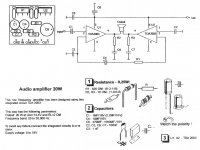
Here's an inexpensive little amp suited for a table radio (with a surprise).
It needs a 10k pot and it needs regulated power.
The surprise: It will fill approximately 125 cubic foot of air with a large 3d sound field from a single speaker.
What causes the surprise Big Wide Tall Deep sound field size (from a single speaker) feature from this little thing?
Attachments
Hi Ken! Which of these easy to find fets do you like best? 2n7000, 2n7002, VN2222LL, BS170, IRF510, IRF530, IRF540, IRF610, IRF640, IRF710, IRF730, IRF740, IRF820, IRF830, IRF840, IRFBC40, IRF3205, IRFZ20, IRFZ24, IRFZ44, IRF9540, IRF9610, IRF1010, MTP3055VSome of the bigger MOSFETs like IRF510 simulate well too. . .
If I get the parts order in now, it may arrive in time for my off week; but otherwise, yet another week delay while I'm at work. So, which is best?
Woudn't know without trustworthy spice .models to simulate them all.
I gave you the complete simulation a few posts back, nothing keeping
you from trying whatever you wish.
I've simmed 2n7000 and 2n7002, and vn2222, and found them not to
have sufficient gain for this application. Divide tranconductance by the
total energy stored in Miller (QGD?) should give you a figure of merit
that might point to suitable candidates. Or at least help weed out
those that are grossly unsuitable.
Though I have not run any of these maths yet, I would lean to 9610.
Just a gut instinct that one might not disappoint? And if it does, you
can still use for plenty of other things.
Last edited:
Thanks Ken!
These two are competing with Christmas packages:
IRF9610 (10 of them from Texas)
1N5237 8.2v (5 of them from Arizona)
Also have a small amount of dramatically marked up off brand IRF510's from the Radio Shack.
So far, power supply looks like:
24v EI transformer, 1N5407//10nF, 3300uF, choke, 1000uF, LM317HVT, 10uF//300uF, cable.
Doesn't that look like I should use a 28v transformer? As in drop more volts and maybe drop more noise?
Thank you.
High Availability Zetex (of the series mentioned) includes: zvn2106, zvn2110, zvn3306
High Availability Zetex (of the series mentioned) includes: zvn2106, zvn2110, zvn3306
LOLZ!!!! OP275's came in. They are the size of ticks. No wonder that was on sale.
I got gel flux in my mustache and it tastes really bad!!
I got gel flux in my mustache and it tastes really bad!!
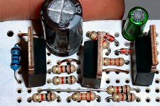
Been chasing down Fake Fets with the car! These IRF9610 Fets from Texas arrived at my mom's house in Kansas, so after a 4 hour drive, I caught them, but they weren't Texans. By looks, extremely shiny thin chrome with much exposed copper on the sides and a few mill marks showing, they are Chinese Fets.
Fortunately, these aren't the well decorated high priced counterfeits with fake brand names on the outside and nothing useful on the inside.
Instead. . .
These are the very inexpensive generic and the manufacturer actually does intend for them to work although it cannot match a simulator. It can be expected to sound more like a 6n11/6n3P than a 6922, will have different voltage tolerances, and won't quite match IRF9610. Fortunately Ken's circuit has some adjustable dials. Thanks man!
I'm sitting down with the schematic, a little board, a scrap of datasheet, some random resistors and 3 fets to discover how to fit this all together without long leads/traces. So far, its not boring. A tone like 6n11/6n3P except also with the clarity that a Fet could do, would be acceptable.
The 8.2v Zeners are authentic NOS Motorola. That's ironic. 🙂
Tom, I've got a sort of question. . .
http://www.diyaudio.com/forums/chip...vs-t-amp-how-do-they-compare.html#post2664589
In that post (#11), the commentary shows the MyRefC making a clear win on soundstage size. Using process of elimination, the beneficial feature isn't caused by the output device. And mine doesn't do it either. Clues on this feature are scarce.
Nesting, it seems, is a valid option for promoting a larger soundfield. Is that correct?
Last edited:
I'm probably clueless but I'll see what I can let out of my brain that I might not know is in there...
The soundstage "image" (more like a movie, I guess) is ALREADY IN the source material. The amplifier can either let it out or not (or does it depend mostly on the speakers?). If I had to guess how an amp might not be able to do it, I'd have to first guess that it would be because the amp is less than accurate at reproducing the source material. But in what way? Intuitively, it seems like it would have to be "bad timing", essentially, because if everything (sound-wise) got to the right place in space at the right time, well there's your soundstage "image", at any instant. I'd then guess that if the reproduction of transients (rising and falling edges, etc) wasn't done well, it might mean that the amp wasn't doing a good-enough job at reproducing the information needed to form the image well-enough for our brains to "see" it. i.e. Maybe the edges are too "out of focus" (or in the case of a digital amp, maybe something like too much jitter could also make the image unrecognizable, like when an old mechanical movie film projector "vibrates" or jerks rapidly; all the light still gets onto the screen but it's too "scrambled" to look like an image.).
Anyway, in an analog amp, I might guess that an insufficient decoupling capacitance implementation might cause it, because complex waveforms (i.e. everything except a pure sine wave) can only be accurately reproduced if each frequency component has both its amplitude and its phase angle reproduced accurately. [You can literally exactly reproduce any complex steady-state waveform by summing an infinite number of pure-sinusoidal components, each with the correct amplitude and phase angle (see "Fourier Series", and then see "Laplace" to include non-steady-state too, not to mention solving time-domain differential equations by first Laplace-transforming them into plain algebraic equations in the frequency domain, and then inverse-Laplace-transforming the answer back into the time domain).]
Anyway, if your decoupling caps, when combined with the series inductances that connect them between the power pin and the load ground pin, plus their internal inductances, can't provide the current needed, exactly when it's needed, in order to produce any transient current profile that the device/power-rail combo "should be" physically capable of sending to the speakers, then obviously something will be lost. And maybe that would include the soundstage image.
Let's see... LM1875... 7 Volts per microsecond, up to about 28 Volts max, with up to 4 amps into an 8-Ohm load.
i = C dv/dt is the classic differential equation for capacitor behavior. i.e. Capacitor current is capacitance value times the time-rate-of-change of the voltage across the capacitor.
So, roughly, and also solving for C, C = ipeak (delta t / delta v). But in the case of a decoupling cap for which we get to select a value, the delta v is the amount of voltage variation that we want to allow on the power supply rail that's being decoupled.
So, for an LM1875, if at its max slew rate for as long as possible, it could go from 0 Amps to 4 Amps, in 4 microseconds. So we need a capacitance of at least C = 4 Amps (4 us / delta v).
If we want to allow the power rail to be disturbed by 0.1 Volt or less, then C = .000160 F, or 160 uF, or more. Or, to only allow a .01 volt variation when that massive transient struck, we would need to use 1600 uF or more.
However, that assumes that the capacitance and the interconnects are ideal, with no series resistance or inductance. In reality, make both of those parasitics very small, or add more capacitors, in parallel.
Thinking about it another way (in order to be able to account for stray inductance and capacitor ESR), 0.1 Volts divided by 4 Amps gives an impedance of 0.025 Ohms, which is what the power and ground pin need to see across them, from whatever is supplying the current, at the frequency that's equivalent to the transient event. If we just use the highest frequency, that should be sufficient. It turns out that the frequency equivalent for a rise time, trise, is f = 1 / (Pi x trise), which can also be solved for trise to get trise = 1 / (Pi x f). Our 4 us gives f = 79.6 kHz. The LM1875 datasheet says 70 kHz, which is close. 70 kHz gives an equivalent trise of 4.5 us.
An inductor's impedance component due to AC frequency (i.e. not including DC resistance of the wire or trace) is ZL = (2 Pi F L) and a capacitor's is ZC = 1 / (2 Pi f C).
At 70 kHz, our 160 uF cap would have an impedance of 1 / (2 Pi 70k 160u), or .0142 Ohms. So far so good. But we'd have to add in the impedances of the cap's ESR at 70 kHz and its ESL at 70 kHz. Then we'd have to add the inductive impedance of the leads and PCB traces at 70 kHz. With 30 nH of lead and trace inductance, we'd have another 0.013 Ohms right there, at 70 kHz. That's already too much, at .0272 Ohms! And we haven't even included the cap's ESR or ESL.
So we'd need to parallel some more 160 uF caps, or, increase the capacitance value. Let's see, for 330 uF at 70 kHz, the impedance would be about .0069 Ohms. So that might work, if we didn't have to worry about the ESR and ESL.
We should also note that with the PCB trace inductance, we could use up the whole allowance of .025 Ohms if the inductance was only 57 nH, which would be extremely easy to achieve, probably with a couple of inches of PCB trace length from the power pin to the cap and the cap to the gnd pin, especially if the traces weren't right next to each other the whole way, with only a tiny gap between them.
But, the total inductance would become SMALLER than any of the individual inductances if we placed the inductances in parallel (just like resistances do). And that would include the internal inductances of capacitors placed in parallel, and the inductances of the traces that connect them to the power and gnd pins! The catch is that the total of the inductances WON'T get much smaller if there is mutual inductance between them. What that means is that the parallel paths must not be the SAME path. So each added parallel cap would need its own set of two traces (or wires, or leads, or... ground plane path) to the pins.
Also remember that we first have to place two X7R multi-layer ceramic caps, to connect directly between each power pin and the load ground pin.
A ground plane is starting to look better and better.
Last edited:
Or, as you wondered, maybe "nesting" (putting the power amp(s) inside the feedback loop of a good opamp) could be better than un-nested, if the nesting is done well. My simulator usually seems to think so.
Or maybe the Howland Current Pump topology of the MyRef is just better at providing an accurate reproduction the "more important parts" of the source material than a standard negative feedback loop topology is.
By the way, the Howland topology is not the same as "nesting", in the usual sense. It has both positive and negative feedback loops, and makes a true voltage-controlled current source. And it can be quite agile in its response.
National.com has a good relatively-recent appnote, number AN-1515 I think, by the late, great Bob Pease, that's all about the Howland topologies. Good stuff.
Actually, I think that almost any topology or type of implementation can be made to image extremely well. I'd guess that it mostly depends on the layout and implementation/design details, and that it's which of those details might be most significant, in certain topologies, that we're trying to determine, or at least think about.
I will say that with a standard nested feedback loop topology, you can see a sort of "pre-decoupling"-looking effect, in the signals sent from the controlling opamp to the power amps inside its feedback loop, especially, for example, when the input signal is a pulse train. If the power amplifiers aren't quite agile enough, the feedback loop topology is smart-enough to cause the opamp to send exaggerated edges (with "spikes" extending upward past the leading edges and downward past the trailing edges), to sort-of precisely "goose" the power amps into producing faster and more-perfectly-shaped rising and falling edges. The outer feedback loop will also even include smaller opposite-direction spikes in order to force the power amps to instantly stop the rising or falling edge and form precisely-shaped corners on the pulses, with no overshoot or ringing.
Last edited:
Thanks Tom! I would agree on your power circuit examples. However, changes to sound field depth with power circuit run exactly in proportion to changes in clarity. Clarity/Resolution of the power circuit is sound field depth, but doesn't make any large changes to sound field width.
I think it might be very interesting to consider a 1.5k to 4.7k feedback resistor and with the gain setting quite low, in addition to feed forward to help make for normal gain.
There are some "very interesting" effects possible by putting some of the inverting signal into the non-inverting input or putting some of the non-inverted signal into the inverting input.
These can have some effect on the sound field width of a monophonic amplifier.
P.S.
There are some BJT that I find "Very Interesting" and that is NXP BCP56/BCP53 instead of discontinued unobtainium NOS Philips BD139/BD140 which is a higher performance part than same part number of today, and that makes repairs hard to do, except. . . It wasn't discontinued, but rather it looks like this thing 🙂NXP BCP56 Tryin to fix my radio AF section and discovered that the part wasn't unobtainium after all. It is renamed, shorter size and the tab is solder affixed rather than bolt affixed. It is less convenient, but not gone.
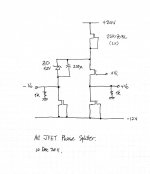
N-Channel on Schematic, P-Channel on circuit board. Help?
At Post 54 the schematic has an N-channel Mosfet
At Post 68 the recommended part is a P-channel Mosfet, and I bought them.
Do I just turn over the caps and reverse the power polarity, pretty much like Dr. Who's fix for anything electrical?
Basically. . . Help!
At Post 54 the schematic has an N-channel Mosfet
At Post 68 the recommended part is a P-channel Mosfet, and I bought them.
Do I just turn over the caps and reverse the power polarity, pretty much like Dr. Who's fix for anything electrical?
Basically. . . Help!
- Home
- Amplifiers
- Solid State
- Fet based phase splitter?