Ah, right, I was somewhat mixed up 🙂Can't quite understand a few of things in your description:
"OP275 as a bridge amp itself" - What does this mean? "driving a 2 channel power amp" - Feedback can't be for two channels at once...
I think it looks like (only talking about the right channel amp):
One OP275 (that also does phase inverter duties) driving Two power amplifiers.
And then nesting.
Yes that is global feedback for two at once--one is inverted phase.
Well I just didn't want to talk about nesting with a bridge amp and accidentally omit the phase inverter job. 🙂
Staring at that is why I was mixed up."equipped with common mode feedback" - What does this mean?
Here it is: SuperSymmetry Common Mode Feedback <----- link
Just scroll down to the schematic on common mode feedback.
It seems to be the most complicated solution to using feedback and it sound like you didn't. If you didn't go off your chair yet, click on that link. 😉
It looks like cross feed shunt reg? That schematic makes me dizzy and confused.
Ah, right, I was somewhat mixed up 🙂
I think it looks like (only talking about the right channel amp):
One OP275 (that also does phase inverter duties) driving Two power amplifiers.
And then nesting.
Yes that is global feedback for two at once--one is inverted phase.
Well I just didn't want to talk about nesting with a bridge amp and accidentally omit the phase inverter job. 🙂
Just consider the dual OP275 package and the two bridged power amps to be one big booster amp and then get another opamp to wrap around the whole thing. Yeah, the "what's the feedback?" question... Maybe have a voltage divider on each output (the two bridging power amps) and then have a differential amp or instrumentation amp across the voltage divider outputs, and then send its output back as the feedback? I'm on my way out the door so I'll have to sketch it to see if that even makes sense (later!). Or maybe just have two feedback loops, one for each phase, IF the OP275 circuits are independent, anyway. I guess I have to say that I don't know yet, at this point...
Staring at that is why I was mixed up.
Here it is: SuperSymmetry Common Mode Feedback <----- link
Just scroll down to the schematic on common mode feedback.
It seems to be the most complicated solution to using feedback and it sound like you didn't. If you didn't go off your chair yet, click on that link. 😉
It looks like cross feed shunt reg? That schematic makes me dizzy and confused.
I'll have to check it out later. I'm on my way out the door.
Thanks man!
I was going on the assumption that its easiest to nest when the small signal op-amp is inverting. Therefore I need a differential line driver with BOTH sides of op275 inverting. There wasn't any in chapter six. The single supply edition with both sides non-inverting might work, but stability issues? What do you think is the best approach (with both sides same)? 🙂
Maybe you could try the dual OP275 "inverter-follower" differential line driver circuit that's shown in Figure 6-54, which is in the downloadable PDF of chapter 6 at ADI - Analog Dialogue | Op Amp Applications Handbook . (Of course, other opamps could be used, instead of the OP275.)
You could also look at the topology in Fig 6-96 (and 6-120, for future reference).
I was going on the assumption that its easiest to nest when the small signal op-amp is inverting. Therefore I need a differential line driver with BOTH sides of op275 inverting. There wasn't any in chapter six. The single supply edition with both sides non-inverting might work, but stability issues? What do you think is the best approach (with both sides same)? 🙂
Thanks man!
I was going on the assumption that its easiest to nest when the small signal op-amp is inverting. Therefore I need a differential line driver with BOTH sides of op275 inverting. There wasn't any in chapter six. The single supply edition with both sides non-inverting might work, but stability issues? What do you think is the best approach (with both sides same)? 🙂
Now I'm confused. If both sides were inverting, then it wouldn't be differential, and wouldn't work as a phase splitter, would it?
Now I'm confused. If both sides were inverting, then it wouldn't be differential, and wouldn't work as a phase splitter, would it?
Sorry man. I was asking because I don't know. The non-inverting single rail example from chapter 6 does look extremely handy as for maybe avoiding adding yet more buffers, avoiding ground loops and avoiding hard wiring the speaker return noise into the pre ground plane. So, it does have a lot of good news. Its probably possible to add some supplementary global feedback without freaking it out. But, it might be a lot less feedback doing a lot less of what you intended.

Just for fun and curiosity, is it possible to make something very much like the MooseFet IRF710, except with the major difference being phase splitter duties for bridging amplifiers?
What about a differential line driver opamp?
http://www.ti.com/lit/ds/symlink/drv134.pdf
http://www.ti.com/lit/ds/symlink/drv134.pdf
17 volts into 600 ohms with a slew rate of 15V/us @ 0.00005% THD.... If that's not good enough...
Last edited:
http://classicvalve.ca/docs/MooseFET_docs_v1.pdf There is the moosefet preamp with schematic. Howabout a phase splitter much like that?
But, really most any fet based concertina / phase splitter would be interesting to try. Failing that, well, just please "anything" more interesting than yet another boring DRV134. 😉
dirkwright,
Yes, that would be perfect.
But read the last sentence of his second post.
Cheers,
Tom
What do you think of this curious arrangement?
Is there something that needs fixed?
Surely there would also have to be 4.7 pF from each output to negative input, just to bolster the "4.7" theme. <grin>
dirkwright,
Yes, that would be perfect.
But read the last sentence of his second post.
Cheers,
Tom
Oh, duh! I wasn't paying attention.
But, I don't understand the need to make this thing "interesting". I suppose he could duplicate the entire circuit using Nuvistor tubes... but hey, why make this hard?
Watch out for practical!
A DRV134 application: Buffer > DRV134 > Cable > INA134
Looks like this: Compensation > Compensation > Inductor > Compensation
Sound good yet?
Yes, I do own a pair of DRV134--This is not less embarrassing than a bad stumble while carrying the cat litter box. Its disturbingly similar. The consequences to audio are kind of the same.
Past performance as a predictor of future outcome:
The embarrassment is from paying more for a job that 4580 is proven to do better at 1% of the cost. Proof? Sure. Check the output of your M-Audio, which also happen to be practical for audio. A proven history of performance indicates practicalities for performance. As for easy, why not find some broken sound cards and recycle free materials that actually work for audio?
Since a fundamental compensation overdo error is sealed inside the DRV134 chip, it cannot beat a discrete design. Its not even close to being practical for audio amp use. Perhaps one can attempt feed forward to remove the overdo mistake from a unity or near unity stabilized chip?
Otherwise: Application Mismatch
P.S.
The OP275 circuit posted far above, practically beat the performance of the 4580 example here. These are a practical step in the right direction. A discrete solution could do even better.
DRV134: A highly compensated part that measures well and doesn't perform for audio. That's not practical.Oh, duh! I wasn't paying attention.
But, I don't understand the need to make this thing "interesting". I suppose he could duplicate the entire circuit using Nuvistor tubes... but hey, why make this hard?
A DRV134 application: Buffer > DRV134 > Cable > INA134
Looks like this: Compensation > Compensation > Inductor > Compensation
Sound good yet?
Yes, I do own a pair of DRV134--This is not less embarrassing than a bad stumble while carrying the cat litter box. Its disturbingly similar. The consequences to audio are kind of the same.
Past performance as a predictor of future outcome:
The embarrassment is from paying more for a job that 4580 is proven to do better at 1% of the cost. Proof? Sure. Check the output of your M-Audio, which also happen to be practical for audio. A proven history of performance indicates practicalities for performance. As for easy, why not find some broken sound cards and recycle free materials that actually work for audio?
Since a fundamental compensation overdo error is sealed inside the DRV134 chip, it cannot beat a discrete design. Its not even close to being practical for audio amp use. Perhaps one can attempt feed forward to remove the overdo mistake from a unity or near unity stabilized chip?
Otherwise: Application Mismatch
P.S.
The OP275 circuit posted far above, practically beat the performance of the 4580 example here. These are a practical step in the right direction. A discrete solution could do even better.
DRV134: A highly compensated part that measures well and doesn't perform for audio. That's not practical.
Here's the DRV134 schematic. Show me where there is "compensation" in this circuit.
The rest of the stuff you wrote makes no sense to me. sorry.
Attachments
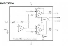
Yes sir. A1, A2, A3 clearly show a grouping of internally compensated buffer chips. My application doesn't resemble an IN134 closely enough for DRV134 to produce the favorable figures that it did within optimized circuits located at the laboratories of Texas Instruments.Here's the DRV134 schematic. Show me where there is "compensation" in this circuit.
Unfortunately, there is nothing in common.
This was and remains, Application Mismatch.
If you can apply it successfully to drive a hi fi power amp, well Kudos. But the facts are that I cannot.
Biggest PITA was getting both clipping behaviors right.
If you are bridging an amp, I would assume that both
drives need to clip exactly the same??? And not pump
one side up while the other down, nor make weird dip
in one peak asymmetrical to the other...
Finally solved: let clamping find it's own damn center.
That worked! Nothing "normal" I tried before that did...
VGS threshold sets how close to our rails that a clamp
must restrict the input waveform. These zeners give us
about 3.1V exclusion, but I think it wants for around 4V.
Might also keep drains from going severely non-linear.
Some of the bigger MOSFETs like IRF510 simulate well
too, but the tail resistor at the bottom also has to be
scaled with VGS. Probably ought to be a potentiometer.
I could not find a lower VGS .model that performed well
enough to keep the gains balanced with reasonable low
output impedance. The one chosen for this sim isn't too
bad, but it is surface mount.
Sim here is just starting to clip. Back the input down a
little, if you prefer to examine the linear performance.
Attachments
Last edited:
Ken, that looks great!
So, R5 is 270R (or 330R?) parallel to 1k variable resistor and turn the dial till 3.12v?
Surface mount fet is okay. They're easy to solder.
What other adjustments are done when "Fet Rolling" 🙂
For IRF510? (fast local availability for it too)
For IRF710?
I mean, do some of the other resistors need to be different value or variable to support that?
Which resistors need to be larger than 1/4w?
The Zener is 8.2v 1/4w. But I have 9v on hand. Okay to try it?
Ignore 3.12V. Tweak the pot till outputs are centered
exactly halfway between GND and power. Whatever
voltage VGS turns out to be, probably doesn't matter...
9V is too wide, it won't clip in time to keep the circuit
in the zone of good behavior. If 9V is the reverse volt,
you have to add another 0.7 for the opposing diode
that is biased in the forward direction, so total its 9.7.
Unless you speak of an SA9 transorb. Bidirectional, so
you would only be using one...
Don't go closer to the rails than VGS. And don't use
a MOSFET with low VGS. We lose open loop gain, and
closed loop gain balance if VGS and R5 are too small.
Pick a zener thats a little smaller than (B/2)-VGS, or
add a few volts to the rail to widen your margins.
Last edited:
And R7 33K might do well to be a 50K pot.
It cuts some gain from the left side to better
match the right. Like all see-saw paraphase,
takes a small imbalance to drive the other
half... But we can shave that off at the end,
and make them exactly equal.
It cuts some gain from the left side to better
match the right. Like all see-saw paraphase,
takes a small imbalance to drive the other
half... But we can shave that off at the end,
and make them exactly equal.
I think that I understood the voltage. But, I don't understand which pot dial to turn to make the outputs have the same voltage (both at exactly 1/2 the rail). Earlier, there was also mention of pots and adjustments, but I became lost, since the schematic doesn't show it.
Last edited:
We have to multiply VGS to center the output between GND
and the power rail. But we won't know VGS in advance...
My voltage marked "3.12" is a manufacturing variance of the
MOSFET, and not something you can control. No matter how
far out of wack you might adjust this circuit, you will always
find VGS threshold for your M3 here, whatever number that
threshold happens to be. Probably not the same as mine...
Instead, adjust R5 until DC offset of your output is 1/2 of
full rail voltage. For 24V rail, use 12V. For 30V rail, use 15V.
Both outputs DC should be same, so doesn't matter which
output you choose to probe for the R5 adjustment.
After you get the center set, you can measure VGS at the
point marked "3.12" if you are curious to see what figure
your MOSFET threshold might actually be... It matters to
your selection of a proper zener threshold.
The thresholds of (one reverse biased zener + one forward
biased zener + M3) should not total up more than 1/2 rail.
If they do, pick a smaller zener.
Your 9V zener might be OK at 24V rail with some MOSFETs,
and not with others. Eliminate the worry by using 30V rail.
------
The above measurement was made with no input signal.
But now we need to apply a steady tone that does not clip.
Measure the AC voltage of both outputs, and tweak R7 to
make them exactly equal.
Last edited:
R7, a 68k resistor parallel to a 100k variable resistor?
R5, a 330 ohm resistor parallel to a 1k variable resistor?
*I was aiming for trimpot controls that aren't twitchy and don't wear out the trimpots. For less wear on the trimpots, perhaps the paralled fixed resistors could be a step smaller value. Am I on the right track?
If I heard you correctly, it seems like you want R5 to stay inside the range of 3.3v to 4v. Is that right?
At power up and power down condition, the rails will fall below the range of 24-30vdc. Is that a problem?
Apparently, I need to use an adjustable regulator, so I can dial the rail up or down to help the conditions all match up. Wouldn't that be good?
As for power, I wish that I could calculate the method for making an ordinary regulator chip work as a shunt regulator, like Jan posted in the last newsletter. But, I can't seem to get a grip on the calculations for it. Clean ground and clean voltage would be nice though, because it seems like there's no point in having one clean without the other just as nice. Help?
And I need to order some parts.
While shopping I discovered. . . a point of failure issue.
Although IRF510 is in almost every shopping mall in the USA, here's a longer list of High Availability parts:
2n7000
2n7002
VN2222LL
BS170
IRF510, 530, 540
IRF610, 640
IRF710, 730, 740
IRF820, 830, 840
IRFBC40
IRF3205
IRFZ20, Z24, Z44
IRF9540
IRF9610
IRF1010
MTP3055V
Since availability is a commonplace point of failure, my terrible question is which of the High Availability Worldwide parts on this list would you like to see stuck into your design? I'm sorry to ask this kind of question, but there's more than a few good reasons, such as more accessible, often far less expensive, and defense against discontinuance. So how about a low volume DIY-centric design using broadly available parts? Perhaps not quite so easy as stopping at the mall to pick up a phase inverter. . . but almost as easy as that? 🙂
And, do you have suggestions as for other parts that I should probably order at the same time?
Thanks Ken!
- Home
- Amplifiers
- Solid State
- Fet based phase splitter?