First correct the mistake with the 1M bias resistor and AC couple the input (!!)
The problem with a simple circuit like that will be poor linearity and EMI susceptibility. The latter you can simulate by adding an AC bias to the voltage rail deliberately.
Firstly decent decoupling is needed to prevent 24V rail noise from going straight into the top output unattentuated.
The non-linear response of the device is reduced by the local feedback, but it will still be there - JFET transconductance is not very high so this is a circuit that a BJT will handle far better.
Biasing the input so the bottom output is at about 1/4 the supply allows maximum output swing and reduces the dependence on individual device characteristics.
Just for fun and curiosity, is it possible to make something very much like the MooseFet IRF710, except with the major difference being phase splitter duties for bridging amplifiers?
Any simple discrete circuit you use here will produce a lot more THD than you suspect, and depending on the quality of the PAs being driven, the splitter might swam,p their distortion.
The usual opamp solution is to have a buffer drive an inverting stage, taking outputs from both opamps. The inverting stage will need a small compensating cap to adjust its frequency response. On the other hand, the buffer can be fitted with a feedback R and C to tailor its response as well.
An alternative is to use two inverting stages cascaded.
The mosfet or BJT used as a concertina equivalent has been around for almost as long as these devices have existed. Just like the tube version, the output frequency responses are dissimilar unless you buffer the collector/drain output. It is surprising that the BJT will provide wider response than the mosfet.
How about this one from:Metaphrase Phase Splitter
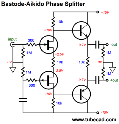
I like the ideal that "....and the bottom FET is presented all of the negative power-supply-rail noise, which we assume is identical to the positive power-supply-rail noise, same in magnitude, but differing in phase. The 10k source resistor, the one that sits between the the two FETs, sees both the input signal and the negative power-supply-rail noise imposed across its leads, which develops a corresponding AC variation in current flow, which then flows through both 10k drain resistors. The input signal gets inverted at the top 10k resistor's connection to the NPN transistor's base, while the bottom 10k resistor presents an in-phase signal tot he PNP transistor's base. Thus, we have our two phases of output signals." according the webpage.
However, when I try simulate it on LTSpice using the beloved jfet 2sk170/2js74, the output look wired. May be I doing something wrong. Please help see if there is issue on the schematic or I did somehting wrong by replacing all 4 with jfet. I changed some register value from 10k to 2k to keep the Idss in-check with the BL grade jfet.
Attachments
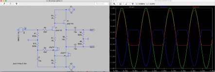
Think I figured out the issue on above schematic. While the writer mention the above circuit for two fet and two transistor (BJT?). The first stage of fet is not bias correctly for 2sk170/2sj74.
I modify the circuit and changed it to use voltage-divider bias at first stage jfet and it work on simulator correctly the first try. Then I find out the new circuit is almost similar to the writer second circuit which using 4 transistor. Anyway. it been good for me and able to learn more on jfet bias as part of discovery and trial and error.
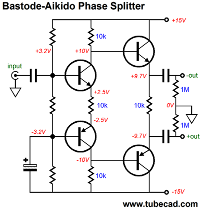
just using two n channel jfet on the upper part and p channel jfet on the lower part.
I modify the circuit and changed it to use voltage-divider bias at first stage jfet and it work on simulator correctly the first try. Then I find out the new circuit is almost similar to the writer second circuit which using 4 transistor. Anyway. it been good for me and able to learn more on jfet bias as part of discovery and trial and error.
just using two n channel jfet on the upper part and p channel jfet on the lower part.
Almost every of the circuits shown stupid after desymmetrization of the output (short circuits pin 1 + 3). Sometimes there is an error with shorting pin 1 + 2. But anyway, in both desymmetrizations, no distortions can occur. Silence yes, but no distortion.
P.S. In practice, Jfet Nch vs Pch never gives a perfect amplification. So as a rule it is better to concentrate on Nch. Principle one SIMPLE, principle two RELIABLE, principle three resistance to OVERLOAD
Yes, it will give amplitude, but it is still a bipole. High internal impedance with low Vgs has only advantages, but Jfet sounds more natural.
options
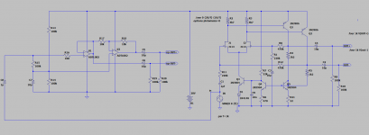
I played with this a bit. Interesting that circuits that use no feedback suffer from wasted output capability, < half the supply voltage. So I turned to a circuit similar to the "Educational PA amplifier" example that comes with LTC Spice. It has similar startup problems but using JFETs that conduct with zero (startup) bias solves that problem. So here it is along with a standard op-amp solution, which could be just one dual part such as TL084.
I played with this a bit. Interesting that circuits that use no feedback suffer from wasted output capability, < half the supply voltage. So I turned to a circuit similar to the "Educational PA amplifier" example that comes with LTC Spice. It has similar startup problems but using JFETs that conduct with zero (startup) bias solves that problem. So here it is along with a standard op-amp solution, which could be just one dual part such as TL084.
Attachments
- Home
- Amplifiers
- Solid State
- Fet based phase splitter?