Re: feedback distortion hump?
That's exactly what I implied in a previous post on the "Many faces of distortion" thread.
It is moot to heuristically discuss what's good or bad per se. These issues among others is what Control Systems Theory is all about.
Rodolfo
jcx said:I’m all in favor of discussing feedback theory and agree with the oft repeated math behind “distortion multiplication” but in any engineering endeavor we really need to put some numbers on the general principles to keep relative importance of various competing effects in perspective
........
PS as to the main topic I strongly suggest some perusal of feedback courses dealing with “minimum phase” vs “nonminimum phase” systems/networks and Bode’s gain/phase integrals
That's exactly what I implied in a previous post on the "Many faces of distortion" thread.
It is moot to heuristically discuss what's good or bad per se. These issues among others is what Control Systems Theory is all about.
Rodolfo
Thanks for posting that link, it's very clearly explained there. Group delay is true delay, but of course you see the output change immediately because it's only certain frequencies that are delayed, where a suddenly starting waveform applied to the input is wideband.ingrast said:May I respectfully suggest you to check again? Note I am not talking about envelope delay. It may be proved (see for example Appendix here) that they are indistiguishable.
This is how Tektronix at least, made delay lines for its early scopes.
Rodolfo
Distortion is caused by nonlinearity, therefore linearizing an amp is the same as minimizing its distortion.lumanauw said:...Is this how to "linearize audio amps before applying feedback"? It seems the Blameless amp does not contain "how to linearize each stage" but rather "how to get minimum distortion" for each stage...
LUMANAUW
"It seems the Blameless amp does not contain "how to linearize each stage" but rather "how to get minimum distortion" for each stage."
Linearisation has the effect to minimise distorsion.
And the best way to know that you are linearising an amp circuit is to measure distorsion and to try to make it as small as possible at all frequencies of interest.
Note that Self gives some very linear input circuits : coumpound pairs,
Cascomp, etc...
~~~~~~~~~ Forr
§§§
Hi, FORR,
Thanks to you 😀 All this time I have the book, but never pay attention to that section. It's funny how I re-learn a certain chapter only after someoneelse (FORR) pointing it out. I didn't pay much attention to that chapter because of the complex looking cct.
Somehow, what I found in Doug book about "linearizing" is different from what I had in mind before reading the book.I tought it is how to get linear from 0 magnification curve for a certain stage. I tought it is done by large RE (local feedback). It appears that this can be done also by CFP configuration.
In single transistor, the magnification curve is not a linear curve. Does a CFP transistor has a straight linear curve from 0? Is there a webpage where I can see the magnification curve for CFP?
In page 69, Doug mentioned "The Cross-Quad" and "The Cascomp" differential input stage. How complicated these 2 😀 And why I never saw it before in commercial schematics?
About VAS linearity, Doug mentioned that putting CCS in lower side is a way to linearize VAS. I've been doing this all this time, so there is no radical method like I found the 2 above for input stage?
Hi, Mike,
I found in Doug book, he mentioned the "balanced VAS" like you use in Symasim. He mentioned 2 versions, 1 is exacly like you use, and the other one is "attributed by Borbely to Lender"
About the one you use, he wrote this :
One thing that I found is that DougSelf book never mentioned a complementary/symmetrical differential input stage. Why is that? John Curl advise that the symmetrical differential input stage is the ONE to use. Quite contrary opinions.
Thanks to you 😀 All this time I have the book, but never pay attention to that section. It's funny how I re-learn a certain chapter only after someoneelse (FORR) pointing it out. I didn't pay much attention to that chapter because of the complex looking cct.
I agree. It is an effect, but Mr.Evil said it is the same thing, not an effectLinearisation has the effect to minimise distorsion.
Distortion is caused by nonlinearity, therefore linearizing an amp is the same as minimizing its distortion.
Somehow, what I found in Doug book about "linearizing" is different from what I had in mind before reading the book.I tought it is how to get linear from 0 magnification curve for a certain stage. I tought it is done by large RE (local feedback). It appears that this can be done also by CFP configuration.
In single transistor, the magnification curve is not a linear curve. Does a CFP transistor has a straight linear curve from 0? Is there a webpage where I can see the magnification curve for CFP?
In page 69, Doug mentioned "The Cross-Quad" and "The Cascomp" differential input stage. How complicated these 2 😀 And why I never saw it before in commercial schematics?
About VAS linearity, Doug mentioned that putting CCS in lower side is a way to linearize VAS. I've been doing this all this time, so there is no radical method like I found the 2 above for input stage?
Hi, Mike,
Well about No2, if you use currentmirror in input-ltp, you have nearly infinite zout there, giving the need for a buffer to vas,
but this creates new problems like ugly clippingbehaviour.
A cascode to the vas does nearly the same job.
I think the method used in my symasym (having currentmirror in
2nd stage) is a better method to balance the ltp.
I found in Doug book, he mentioned the "balanced VAS" like you use in Symasim. He mentioned 2 versions, 1 is exacly like you use, and the other one is "attributed by Borbely to Lender"
About the one you use, he wrote this :
What do you think about the above quote? Nothing personal here, but I wanted to know your opinion also about the topology you use 😀It gives 10 dB more O/L gain than the standard, but this naturally requires an increase in Cdom if the same stability margins are to be maintained. In a model amplifier, any improvement in linearity can be wholly explained by this O/L gain increase, so this seems (not unexpectedly) an unpromising approach. Also, as Linsley-Hood has pointed out, the standing current throught the bias generator is ill-defined compared with the usual current-sourced VAS; similiarly the balance of the input pair is likely to be poor compared with the current-mirror version. A further difficulty is that there are now two signal paths from the input stage to the VAS output, and it is difficult to ensure that these have the same bandwith; if they do not then a pole-zero doublet is generated in open loop gain characteristic that will markedly increase settling-time after a transient. This seems likely to apply to all balanced VAS configurations.
One thing that I found is that DougSelf book never mentioned a complementary/symmetrical differential input stage. Why is that? John Curl advise that the symmetrical differential input stage is the ONE to use. Quite contrary opinions.
lumanauw said:[snip]In single transistor, the magnification curve is not a linear curve. Does a CFP transistor has a straight linear curve from 0? Is there a webpage where I can see the magnification curve for CFP?[snip]
A transistor is a transistor, it doesn't change depending on the citcuit it is in. But a CFP is in fact a kind of high-gain amp (black) box, like an opamp. By using 100% feedback, the box acts very linear. Even very small errors in the output are fully amplified by the high internal loop gain (in inverse form of course) and cancel to a very high degree those errors. Exactly the same story for any amplifier with high gain and heavy feedback.
Jan Didden
forr said:LUMANAUW
"It seems the Blameless amp does not contain "how to linearize each stage" but rather "how to get minimum distortion" for each stage."
Linearisation has the effect to minimise distorsion.
And the best way to know that you are linearising an amp circuit is to measure distorsion and to try to make it as small as possible at all frequencies of interest.
Note that Self gives some very linear input circuits : coumpound pairs,
Cascomp, etc...
~~~~~~~~~ Forr
§§§
And one must not forget to measure distortion spectra at low output levels and to take into account high order distortion components. That's where Self's amp fails. Error correction is necessary, optimal bias for AB as per Self is not enough.
Pavel,
Error correction per Hawksford will also lead to the spectrum enrichment with higher harmonics, as feedback does.
Error correction per Hawksford will also lead to the spectrum enrichment with higher harmonics, as feedback does.
dimitri said:Pavel,
Error correction per Hawksford will also lead to the spectrum enrichment with higher harmonics, as feedback does.
Dimitri,
per Hawksford probably yes .. 😉
LUMANAUW
"One thing that I found is that DougSelf book never mentioned a complementary/symmetrical differential input stage. Why is that? John Curl advise that the symmetrical differential input stage is the ONE to use. Quite contrary opinions."
Sorry, read Self carefully. He mentionned the complementary/symmetrical differential input stage.
As said by Linsley-Hood, a simple differential stage is, in fact, a push-pull. And a complementary differential input stage is a... double push-pull.
You'll see at Mike Renardson site some critisicism of the double push-pull input stage.
For myself, since it first appears inthe SEA and Radio-Electronics amps circa 1973, I have never seen any valid explanation for it, despite its popularity.
It has two different loops to control the same feedback return point. I suppose than one of the loop (not necessarly all the time the same, due to internal fluctuations) imposes the working point of the whole amplifier.
And, because of DC and HF poor stability, the open loop can't be set as high as with a single differential input stage.
~~~~~~~~ Forr
§§§
One reason is that you get partial cancellation of input bias current.forr said:...complementary/symmetrical differential input stage... I have never seen any valid explanation for it, despite its popularity...
Hi, FORR,
He did mentioned about this in page 85 (in the VAS section) :
Using complementary differential is "balancing a stage that is already balanced"?
Hi, Mr.Evil,
Sorry, read Self carefully. He mentionned the complementary/symmetrical differential input stage.
He did mentioned about this in page 85 (in the VAS section) :
When we are exhorted to MAKE THE AMPLIFIER LINEAR BEFORE ADDING NEGATIVE FEEDBACK one of the few specific recommendations made is usually the use of a balanced VAS-sometimes combined with a double input stage consisting of two differential amplifiers, one complementary to the other. The latter seems to have little to recommend it, as you cannot balance a stage that is already balanced, but a balanced (and, by implication, more linear) VAS has its attractions. However, as explained above, the distortion contribution from a properly-designed VAS is negligible under most circumstances, and therefore there seems to be little to be gained
Using complementary differential is "balancing a stage that is already balanced"?
Hi, Mr.Evil,
I'm not quite capturing this. What does it mean?One reason is that you get partial cancellation of input bias current.
Hi lumanauw !
You have 2 big advantages with a complementary diffamp-input:
1, Inputoffset is nearly zero, as the currents through the base
of the inputtransistors are complementary, so they short out each other.
otherwise you have a constant current through the input giving
a permanent dc-offset, also called inputoffset. The trick is typically
to have them on both sides (+input/-input) identical, resulting in
no DC-offset at output of amp. (for nonsymetrical)
With symetrical input you can discard the inputcap without generating
DC-offset.
2, a complementary diffamp is balanced by nature, without using currentmirrors.
the disadvantage: complementary transistors do not really exist...
(That's why i "gave up" this input)
Mike
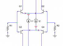
Easiest to explain with a picture, I think. The attachment shows a complementary LTP and the currents flowing in it. Normally the current flowing into the NPN transistor bases is drawn through R1/2, but with the complementary circuit that current is instead drawn through the bases of the PNP transistors. Ideally, the NPN base current exactly matches the PNP base current and thus input bias current is zero.lumanauw said:...I'm not quite capturing this. What does it mean?
Attachments
dimitri said:Pavel,
Error correction per Hawksford will also lead to the spectrum enrichment with higher harmonics, as feedback does.
Dimitri, as I am currently having an interest in Hawksford error correction, this interest me. Can you amplify or give me a reference?
Jan Didden
.
The input offset of a simple differential is zero when using FETs input, and probably very small using a coumpond pair (making the stage very linear) instead of single bipolar for each branch.
Even with a simple differential, is the input offset a problem ?
MIKEB
"A complementary diffamp is balanced by nature, without using currentmirrors."
What do you mean by balance ?
When using a simple diff input, the balance is obtained when the gm of each branch is equal, which means same Re and same current. Here a current mirror load is a big help. The distorsion is minimal at this balance.
Due to fluctuations, as far as I know, a current mirror is never used in dual diff and the current of each N and P branch can never be strictly maintained equal. Then each diff does not work at its best linearity. Another big disadvantage of dual diff is that you have is to try to match the four input and the two VAS devices. A boring task.
I think that the aim of designers using the first dual diff amp was to get a symetrical VAS, in other words a push-pull VAS, in order to deal as fast as possible with the complex and non-linear charge from the output stage.
There are more elegant ways to do a push-pull VAS.
An innovative one I recently saw was on the Halfer site with a circuit called "Diamond". "Diamond" just like an older Sansui circuit which had exactly the same purpose.
Hafler did use a lot dual diff (the first using mosfets at the output were designd by Boberly, I think), and has abadonned it now.
Its novel approach with a single diff input stage is probably less expensive and of higher performances.
~~~~~~~~ Forr
§§§
Hi forr !
With balanced i mean "identical" currents through the ltp-collectors.
Because of the symetric feeding into the vas, a current tending to
the left side of the 2 diffamps would only change the biasing in the
vas, not the outputvoltage. For that reason it's much simpler to
get the 2 diffamps running symetric/balanced.
This looks much different for a singlediffampinput, it's very hard
to get it balanced without currentmirror.
All this of course is only valid with matched transistors.
This is where the topology i use for my symasym becomes very
handy, it has single diffamp input and no currentmirror in 1st stage,
but is perfectly balanced and still has a symetrical push/pull vas...
D.Self is VERY wrong about the "poor" balancing in this topology,
just have a look at the currents in the 1st ltp:
http://www.diyaudio.com/forums/attachment.php?s=&postid=683534&stamp=1121552477
I have verified these currents in realworldcircuit, simply perfect...
Mike
I can confirm Michael's findings.
If you measure the current at the emitter degeneration resistors of a current mirror/LTP you find they are dead equal, no question.]
However, what I believe Self ignores is the bias current for the single ended drive to the VAS.
My criticism does not apply where output is taken differentially, of course, but this approach uses resistive loading with no current mirror.
If the VAS draws 10mA, and beta is 100, then 0.1mA must be supplied from the floating end of the current mirror. If LTP stage current is 1mA, a common figure, then the bias for the VAS unbalances the LTP fully 20%. This is huge unbalance, resulting in high levels of distortion.
Cheers,
Hugh
MIKEB
Balancing seems not to have the same meaning for Douglas Self and me, so you can't say Douglas is very wrong...
As with all circuits using push-pull VAS stage, the cascaded diff amp , pionnered by Hitachi, has problems of compensation. The NPN and the PNP transistors have different Cbc. Many people are puzzled by the right compensation to adopt : only one ? or one for each transistor ? The stability is not guarented at 100%.
Your scheme may be ok but it is not optimal as the load of the VAS is augmented without having the feedback effect of the classical Miller compensation which is very beneficial for linearisation.
Perfection in our world is a very relative world.
Back to complementary input stages and my question. Has anyone an idea of how is determined the working point by the two different loops ?
~~~~~~~ Forr
§§§
This is a good reason to use an improved, high gain Vas such as the EF buffered one that Self proposes, or a Sziklai pair, or a cascoded MOSFET. Doing so will yield an extremely high current gain to well past the audio band, minimizing distortion in the LTP.AKSA said:...If the VAS draws 10mA, and beta is 100, then 0.1mA must be supplied from the floating end of the current mirror. If LTP stage current is 1mA, a common figure, then the bias for the VAS unbalances the LTP fully 20%. This is huge unbalance, resulting in high levels of distortion.
- Status
- Not open for further replies.
- Home
- Amplifiers
- Solid State
- Feedback delay & distortion