Forr wrote:
This is only true for designs using a dominant pole, there are other better ways of creating stability and keeping high open loop gain, either with multipoles or by using phase correction networks ala Bode.
BTW, it is very interesting thread, I must say I agree with PMA, the easiest way to avoid any problems with feedback is to keep BW high and good linearity for the open loop, I can't see how there can be any delay or phase problems in that case.
Regards Hans
As wide open loop bandwith is only obtained by reducing the open loop at low frequencies, it is not an efficient cure.
This is only true for designs using a dominant pole, there are other better ways of creating stability and keeping high open loop gain, either with multipoles or by using phase correction networks ala Bode.
BTW, it is very interesting thread, I must say I agree with PMA, the easiest way to avoid any problems with feedback is to keep BW high and good linearity for the open loop, I can't see how there can be any delay or phase problems in that case.
Regards Hans
Hi, FORR,
I remember reading something about "linearizing before feedback" in Doug Self book.
In my book (1st edition) it is on page 44 :
What does Doug Self mean? Is the cct in that book "The Blameless Amplifier" is how an amp is supposed to be after linearization? The "linear before feedback" amp sounds like Doug's Blameless Amplifier?
I remember reading something about "linearizing before feedback" in Doug Self book.
In my book (1st edition) it is on page 44 :
MAXIMISING LINEARITY BEFORE FEEDBACK
MAKE YOUR AMPLIFIER AS LINEAR AS POSSIBLE BEFORE APPLYING NFB has long been a cliche. It blithely ignores the difficulty of running a typical solid-stage amplifier without any feedback, to determine its basic linearity.
Virtually no dependable advice on how to perform this desireable linearisation has been published. The two factors are basic linearity of the forward path, and the amount of negative feeedback applied to further straighten it out. The latter cannot be increased beyond certain limits of high-frequency stability is put in peril, whereas there seems no reason why open-loop linearity could not be improved without limit, leading us to what in some senses must be the ultimate goal-a distortionless amplifier. This book therefore takes as one of its main aims the understanding and improvement of open-loop linearity, as it proceeds we will develop circuit blocks to culminating in some practical amplfier designs that exploit the techniques presented here.
What does Doug Self mean? Is the cct in that book "The Blameless Amplifier" is how an amp is supposed to be after linearization? The "linear before feedback" amp sounds like Doug's Blameless Amplifier?
MBK said:[snip]In any equation of the form d'something'/dt you may make dt arbitrarily small, but not zero. Furthermore feddback at input requires prior output. So by definition feedback must contain an element of "delay" or if that word is taboo because of prior commitment to other uses, then let's call it "order of events" (in my book, another definition of time itself but anyway...).
Mike,
If we connect a signal voltage to a coil, wisdom has it that the current lags the voltage 90 degrees. So, we are tempted to say that there is a signal delay. But, that current starts to flow immediately when the voltage is connected.
In the same way, the feedback voltage at the inverting input is there immediately when the output voltage (containing the error) is there. There is no "after the fact". And that fb has an effect immediately on the Vout: as soon as the immediate fb voltage is at the inverting input, with the same reasoning it also immediately causes changes in voltages and current throughout the amp to the output.
It is however the phase shift through the amplifier that causes the correction to be out of phase with the original error so the correction / cancellation is less than perfect.
OTOH, the delay view is probably equally valid. I remember long time ago when I tried to understand how a scope can display a signal portion before the trigger that caused the sweep to start. Easy: you put the signal through a delay line consisting of C's and L's. Then, when the trigger arrives that starts the sweep, a portion of the signal before the strigger is stil 'present' in the delay line and since the delay line output is connected to the display system, you can actually see something that happened in the past....
Jan Didden
BTW 3000Hz is between the 7th and 8th harmonic of 20Hz.....
lumanauw said:[snip]If we make the same amp with feedback, the differential will not allow any phase shift, it will be wrong for the differential, because the differential works in instant phase, in both bases, input and output. What happened to the "natural phase shift" that naturally should be contained in the CCT, but becomes disabled by the differential pair? I'm not clear here. [snip]
David, see my previous post.
Jan
If we connect a signal voltage to a coil, wisdom has it that the current lags the voltage 90 degrees. So, we are tempted to say that there is a signal delay. But, that current starts to flow immediately when the voltage is connected.
I wish this were explicitly stated in more often. For instance Horowitz & Hill's description of capacitors and inductors can lead one innocently to conclude there is some kind of true delay. Probably if read very carefully this would not be the case but first impressions are hard to overcome.
In the same way, the feedback voltage at the inverting input is there immediately when the output voltage (containing the error) is there. There is no "after the fact". And that fb has an effect immediately on the Vout: as soon as the immediate fb voltage is at the inverting input, with the same reasoning it also immediately causes changes in voltages and current throughout the amp to the output.
A bit more difficult to really "get it". If I close my eyes, make a face and concentrate real hard it come through.
On further cosideration, I think the problem of comprehension is partly that we are so thoroghly taught to reject or at least be suspicious of "action at a distance" and of the concept of simultaneity that the cases where this doesn't apply trip us up.
I think it was A. Clarke that wrote an explanation of how certain events can appear to exceed C. The analogy he used was a wave breaking along a long straight beach. It starts to break at one end and the break point proceeds rapidly along the beach front. The break point appears to move and can move faster than C. It can even be simultaneous. If we assume causality it can even appear to be time travel. The glitch in our thinking iswhen we think that causality points from the immedeate break point to the next, whereas in actuality origin of causality is elsewhere.
I think it was A. Clarke that wrote an explanation of how certain events can appear to exceed C. The analogy he used was a wave breaking along a long straight beach. It starts to break at one end and the break point proceeds rapidly along the beach front. The break point appears to move and can move faster than C. It can even be simultaneous. If we assume causality it can even appear to be time travel. The glitch in our thinking iswhen we think that causality points from the immedeate break point to the next, whereas in actuality origin of causality is elsewhere.
sam9 said:On further cosideration, I think the problem of comprehension is partly that we are so thoroghly taught to reject or at least be suspicious of "action at a distance" and of the concept of simultaneity that the cases where this doesn't apply trip us up.
I think it was A. Clarke that wrote an explanation of how certain events can appear to exceed C. The analogy he used was a wave breaking along a long straight beach. It starts to break at one end and the break point proceeds rapidly along the beach front. The break point appears to move and can move faster than C. It can even be simultaneous. If we assume causality it can even appear to be time travel. The glitch in our thinking iswhen we think that causality points from the immedeate break point to the next, whereas in actuality origin of causality is elsewhere.
Sam,
I have to come out now. If you really, really look hard at it, there is no simultaneity. There is a 'true' delay in any component or circuit. The speed of signal propagation is ultimately limited by C and in practise lower. But what is the delay through, say, 2 inch (5.08 cm) of wire or pcb track? Assume 0.5C prop speed, that comes out to 5.08/15 * 10e-9, lets say 300 picosecs. (Did I get that right?). For perspective, that a 20kHz phase shift of about 3/5*10e-5 * 360 degrees, or 0.0022 degrees.
Now, I don't think even the most die-hard audio freak would say that messes up de feedback. Or anything else.
Jan Didden
LUMANAUW
As previously said, delay at the output of amps using feedback (I very much prefer) or no feedback are so small than they are strictly irrelevant to audio.
One of the advantages of feedback is that is speeds up the output (less phase shift than when using no feedback).
Congratulations for your reading of the D. Self's book. I am unware of any other book dealing so simply and deeply with amplifiers.
Linearisation amp before applying feedback : Self shows some ways to do it. Have a look too at Gerard Perrot's patents (at Free Patents On Line), Halcro patents and Mike Renardson's site.
TUBETVR
"This is only true for designs using a dominant pole, there are other better ways of creating stability and keeping high open loop gain, either with multipoles or by using phase correction networks ala Bode."
I know double pole compensation described by Douglas Self in his book, scheme advocated by John Linsley Hood and Nelson Pass, nested loops by Ed Cherry and scheme by Matti Ottala whose stablity was not very good despite the low feedback.
I would be interested to know other references, if you have them.
~~~~~~~ Forr
§§§
Genuine delay vs. phase shift discussion
By the tune of several recent posts, it looks like my post #78 somehow was overlooked or (probably) I did not a good job of explaining myself.
A couple of observations to abound on this issue.
1. Put into a black box a true delay line (an appropriately long transmission line) making sure it is properly impedance matched at both ports. Put into a second black box a lumped component circuit (designed at will) that approximates to a very high degree a linear phase/frequency dependency at least within a restricted frequency range.
If you test both black boxes within the specified frequency range, they will be indistinguishable.
2. The discussion on whether negative feedback is good or bad is moot if not placed on an actual application context. It will attenuate forward path nonlinearities by an amount depending on loop gain *including the frequency dependency* of this loop gain. To make it clearer, an amplifier with a dominant first order pole at 1KHz and 60 dB of loop gain will improve performance by a factor of 1000 at 1KHz (*), but by 630 at 2KHz and so on, down to by 63 at 16 KHz.
In reality it will be worst, for most probably at 16 KHz additional higher frequency poles may begin to show off. This is only an extreme example of course.
Rodolfo
(*) By 708 actually😉
Rodolfo,
Yes I overlooked your post too. Another missed opportunity to disagree with you 😉 , glad you pointed it out.
I agree to your post, but would like to make one distinction, in that the fb signal doesnot come too late. But, for exact error cancellation the feedback returned error must exactly cancel the original error (must have same waveshape and amplitude but inverted). Because of the loop phase shift, the waveshape is NOT the same, so cancellation is incomplete. The higher the freq, the less complete the cancellation. But the correction signal is not delayed, it is there immediately (give or take 300 picosecs 😀 ).
Jan Didden
janneman said:Rodolfo,
...But, for exact error cancellation the feedback returned error must exactly cancel the original error (must have same waveshape and amplitude but inverted). Because of the loop phase shift, the waveshape is NOT the same, so cancellation is incomplete. ....
There are 2 issues here. First, conventional negative feedback does not attempt to cancel errors but to attenuate them by a target amount. Second, it is largely irrelevant to talk of a distinction among "genuine" or "phase shift" delay as long one understands how signals behave.
For the "genuine" case, delay is a fixed amount independent of frequency, giving rise to a linear Phase/frequency charasteristic.
In the latter case, delay is frequency dependent and this is why the term group delay is used instead. This can easily be visualized for example comparing input and output signals in a narrow bandpass filter when sweeping across the center frequency.
In any case the effect is as you point out, a reduction in the effective correction as calculated, which is what matters.
And as said earlier, within a restricted frequency band it is possible to fake a "genuine" delay (in the previous sense) provided a linear phase/frequency relationship can be achieved as in the case of multiple L-C cells terminated in the characteristic impedance (sqrt(L/C)) and it has nothing to do with the physical dimensions as to propagation speed.
Rodolfo
I've done the actual test and phase shifters doesn't behave as a true delay even in its valid frequency range.
Assuming a string of phase shifters, properly aligned in order to get a consistent group delay up to a certain frequency 'f', when you start feeding a sine wave of a frequency well below 'f' to such a string of phase shifters, the output reacts inmediately showing that sine wave with a very low amplitude that increases progressively until it matches the input amplitude.
The time it takes for the amplitude to sweep is what we could call 'simulated delay'. Note that this has absolutely nothing to do with delaying in time a waveform, though.
Eva said:I've done the actual test and phase shifters doesn't behave as a true delay even in its valid frequency range.
...
May I respectfully suggest you to check again? Note I am not talking about envelope delay. It may be proved (see for example Appendix here) that they are indistiguishable.
This is how Tektronix at least, made delay lines for its early scopes.
Rodolfo
A further comment
Eva:
Note that if you apply a suddenly starting sine signal, it is not bandlimited as it should be for things to work.
If you limit the input signal to the network upper frequency where group delay is still reasonably constant, then the slope of your input signal envelope will be quite slow in comparison, and what you see at the output is a trully delayed copy.
Rodolfo
Oh, figures 5 and 6 of your RF paper describe quite well the enveloppe effect 🙂
And as that paper states, the way to avoid that effect is to use steady state signals within a very small frequency range where the group delay of the filter is nearly constant, like the carriers used for AM and FM signals.
Note that this is of no use for audio, though.
PD: If you bandlimit the input signal, you can no longer add or remove tones, you can only sweep at a limited rate the frequency of the tones already present (more AM and FM stuff). Again, this is of no use for audio, where you will always face the enveloppe effect since such signals are very rich in transients.
The higher the freq, the less complete the cancellation. But the correction signal is not delayed, it is there immediately (give or take 300 picosecs ).
Jan Didden
Looking back to posts #4 and #6, I calculated 1.7ns assuming 0.1C. So if adjust it to your parameters (0.5C) the results are virtually the same. All this talk of phase, RC networks etc caused me to forget about my original reaction.
Eva said:.....
PD: If you bandlimit the input signal, you can no longer add or remove tones, you can only sweep at a limited rate the frequency of the tones already present (more AM and FM stuff). Again, this is of no use for audio, where you will always face the enveloppe effect since such signals are very rich in transients.
As said earlier, you can fake a delay line out of lumped components but only approximately and within a restricted frequency range. This range may include DC for example as in the case of L-C sections terminated in the characteristic impedance.
The restriction in bandwidth implies the input signal must not contain harmonic components beyond it, which in turn limits the slopes. That being the case, it is demonstrated and verifiable experimentally that the device behaves as a genuine delay line.
As for audio applications, unfortunatelly lumped component delay lines are impractical, but under certain circumstances the phenomena surfaces, for example the Linkwitz-Rilley crossover allignment succeeds in a fairly linear frequency-phase relationship affording in turn better beam control. (By way of a fairly constant composite group delay).
Rodolfo
feedback distortion hump?
I’m all in favor of discussing feedback theory and agree with the oft repeated math behind “distortion multiplication” but in any engineering endeavor we really need to put some numbers on the general principles to keep relative importance of various competing effects in perspective
In this sim of an amplifier with stepped gain around a “square law” fet – it is hard to see the feedback induced higher order distortion “hump” amidst the higher order distortion products from the fet’s own nonideal behavior – where it is visible, it is associated with the lowest gain steps, really high loop gain pretty reliably hammers all of the distortion products down to below the noise floor
For higher resolution only the harmonics of the 1 KHz sine are shown in the fft, the green trace is the lowest loop gain – so low that the fundamental output amplitude is ~ 6dB down from the ideal +9 dB output so you need to add 6 dB to the green trace in the distortion fft to decide if feedback has really increased a certain harmonic relative to the lowest feedback case
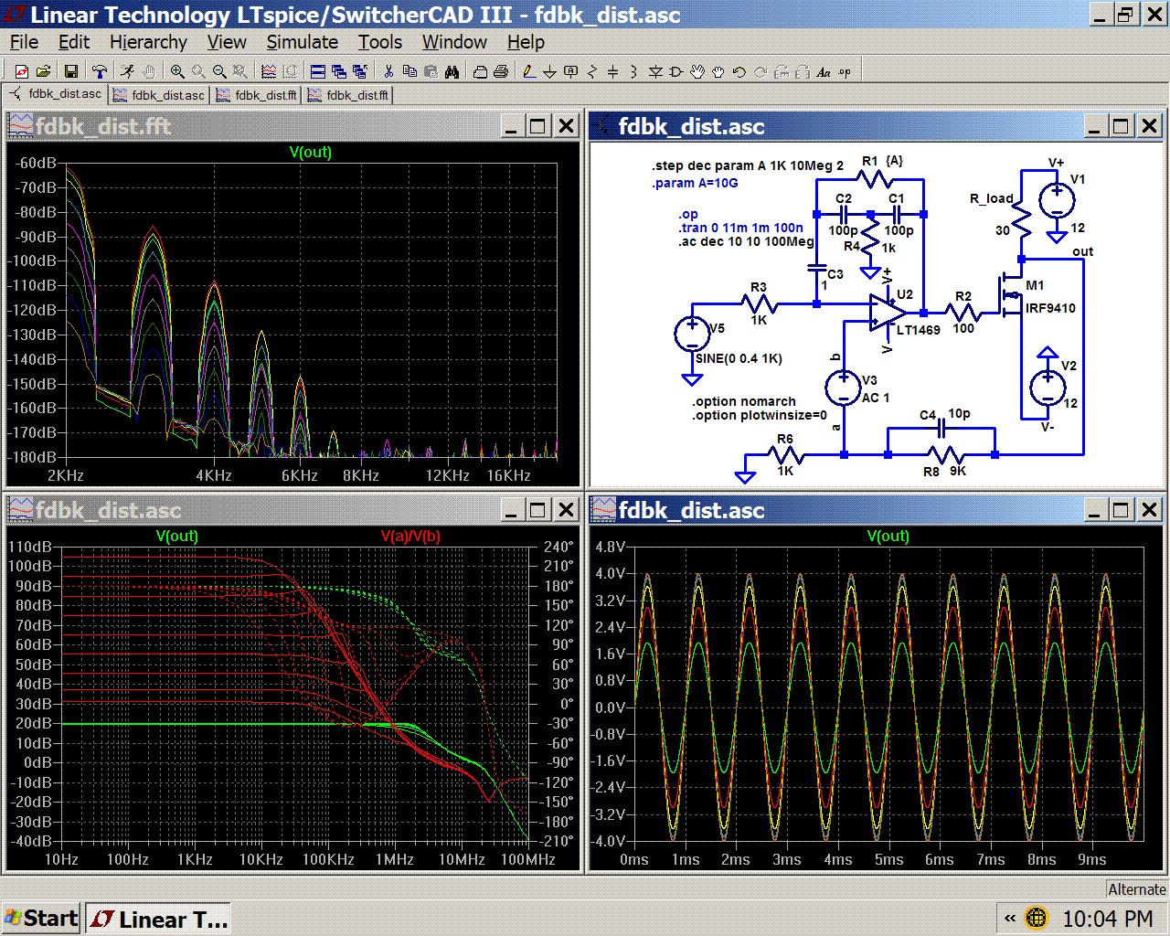
[alternate solver, gear integration, 131K point fft 5 point smoothing filter, Blackman window]
PS as to the main topic I strongly suggest some perusal of feedback courses dealing with “minimum phase” vs “nonminimum phase” systems/networks and Bode’s gain/phase integrals
(LtSpice file; change .txt to .asc)
I’m all in favor of discussing feedback theory and agree with the oft repeated math behind “distortion multiplication” but in any engineering endeavor we really need to put some numbers on the general principles to keep relative importance of various competing effects in perspective
In this sim of an amplifier with stepped gain around a “square law” fet – it is hard to see the feedback induced higher order distortion “hump” amidst the higher order distortion products from the fet’s own nonideal behavior – where it is visible, it is associated with the lowest gain steps, really high loop gain pretty reliably hammers all of the distortion products down to below the noise floor
For higher resolution only the harmonics of the 1 KHz sine are shown in the fft, the green trace is the lowest loop gain – so low that the fundamental output amplitude is ~ 6dB down from the ideal +9 dB output so you need to add 6 dB to the green trace in the distortion fft to decide if feedback has really increased a certain harmonic relative to the lowest feedback case
[alternate solver, gear integration, 131K point fft 5 point smoothing filter, Blackman window]
PS as to the main topic I strongly suggest some perusal of feedback courses dealing with “minimum phase” vs “nonminimum phase” systems/networks and Bode’s gain/phase integrals
(LtSpice file; change .txt to .asc)
Attachments
Hi, FORR,
In Doug book, audio amp is in 3 stages. He do this :
1. Input stage, put current mirror here to get exact balance between legs (he does not say to linearize)
2. VAS, he a buffer (emitor follower) and put miller cap.
3. Output stage, he search for optimal bias voltage. He also does not say this is to linearize, but to get minimum distortion.
Is this how to "linearize audio amps before applying feedback"? It seems the Blameless amp does not contain "how to linearize each stage" but rather "how to get minimum distortion" for each stage.
Could you give me example of what to do for linearizing 3 stages power amp, according to your view?
Hi lumanauw !
Well about No2, if you use currentmirror in input-ltp, you have
nearly infinite zout there, giving the need for a buffer to vas,
but this creates new problems like ugly clippingbehaviour.
A cascode to the vas does nearly the same job.
I think the method used in my symasym (having currentmirror in
2nd stage) is a better method to balance the ltp.
Mike
- Status
- Not open for further replies.
- Home
- Amplifiers
- Solid State
- Feedback delay & distortion