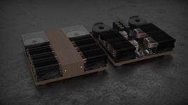
Second to last, but move the power board to the back and down. Definitely fans down. Arrange so the Cinies are up front and visible. 2 cents
Here's a spinoff of that middle version with power moved back and trafos flat. On wood plate or whatever due to larger footprint. Not sure if your fan is 120mm, I just grabbed whatever looked similar from trusty Grabcad-
Attachments


Haze Head for the win. Do we know how the thermal resistance of these CPU sinks compares to standard dissapante sinks?
HH could you share the CAD, I might have a go at some creative ideas 🙂.
HH could you share the CAD, I might have a go at some creative ideas 🙂.
I have to admit when I first saw what you were trying to do I thought, geez, just build a stock example and be done with it. Maybe that’s just the old guy coming out in me but I’m really beginning to like the direction you’re heading. Aesthetics are an overwhelming focus of a lot of commercially available products, seemingly without concern for sound quality. If it looks good that’s more than half the battle to get someone to ante up. I’ve never been in that camp which is why I’m into diy. Of course, not having enough money is undoubtedly a big part of it 🤨
A bit of a diatribe there, apologies.
Nevertheless, I really like the concept in the first picture. Laying the heatsinks over like that just really looks cool. The idea to mount the mosfets remotely is intriguing. It’s different from anything I’m familiar with but in the end that leans towards aesthetics and that’s what got my attention…..hmmm🤔
Best of luck with what appears to be an enjoyable project
Love the idea Haze Head! Was just working on something similar but I like what you've done.
@audioexplorations attached is my Fusion 360 archive - I use the non-commercial version so I'm not sure if there are any limitations exporting/importing/etc. My heatsinks are "Gammaxx 400", which I modeled fairly accurately. The PCB models/etc are close but not perfect.
@audioexplorations attached is my Fusion 360 archive - I use the non-commercial version so I'm not sure if there are any limitations exporting/importing/etc. My heatsinks are "Gammaxx 400", which I modeled fairly accurately. The PCB models/etc are close but not perfect.
Attachments
Last edited:
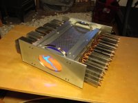
Very cool, thanks for sharing! Are the mosfets & heatsinks all fixed to a common "rail" or something on each side?I like the horizontal layouts the best, they work! Proof of concept below 🙂
@audioexplorations it's a total dumpster fire if you want a full assembly. It just crashes if I try to export to STEP
@mngnt are you able to export to generic formats STEP/IGES/XT, if not, what are your f6 board dimensions?
Here's the link to the Grabcad coolers https://grabcad.com/library/iwongou-12cm-cpu-cooler-1
See post 4922 for the Jensen
@mngnt are you able to export to generic formats STEP/IGES/XT, if not, what are your f6 board dimensions?
Here's the link to the Grabcad coolers https://grabcad.com/library/iwongou-12cm-cpu-cooler-1
See post 4922 for the Jensen
Love these original ideas. Keep in mind the fan(s) have to draw air in from some where to push/pull it through the heatsinks. The fan(s) will energize the air, but there must be a clear path for the air to be pulled in, flow through the heatsink, and be exhausted out. Choking airflow on either intake or exhaust will not cool to full potential and could become noisy.
Also keep in mind that wherever the air is being sucked in from, that's where the dust will come from and flow through the entire path.
Also keep in mind that wherever the air is being sucked in from, that's where the dust will come from and flow through the entire path.
Yes, thanks for the heads up. I actually bought some dust filter material for my PC case, so will be using that.
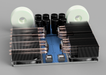
A new idea: Thinking of using a single copper bar on each side for all the chips - which might require remote-mounting the PSU diodes as well. Any reason to not do this?
Single exhaust output via the big fan on top, inlet is the entire baseplate. Not enough space for the transformers but I can figure that out.
(Mounting hardware not modelled)


Single exhaust output via the big fan on top, inlet is the entire baseplate. Not enough space for the transformers but I can figure that out.
(Mounting hardware not modelled)
Last edited:
If the chassis is wide enough, mount the amplifier pcb on the copper plate (larger plate required) and connect the mosfets directly to the pcb.

It seems unlikely that you would need more than 12 dB unless you have a very low output source.
Too bad
lemme see
F6, 25Wrms@8R, means 14.14Vrms
+14db (F6) means 5V/V
+12db (Iron Pre SE) means 4V/V
take it as +26db (14+12) or as 5*4, there you go, 20V/V
so, 14.14Vrms divided with 20V/V, ends with 707mVrms
conclusion, 0V707rms is enough for full blast of F6
while majority of nowaday sources are pumping 2Vrms
go figure
- Home
- Amplifiers
- Pass Labs
- F6 Illustrated Build Guide